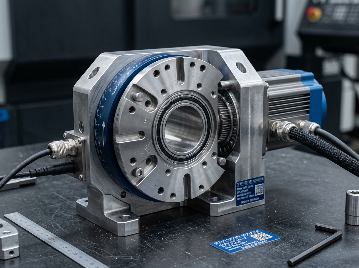
IND-ACT-ROT-140-DD
Verified
Actuators
Rotary Actuators
High-torque rotary actuation module with zero-backlash gearing for joint articulation.
Continuous Outpu…65.0 Nm
Peak Stall Torque195.0 Nm
Rated Speed250 rpm
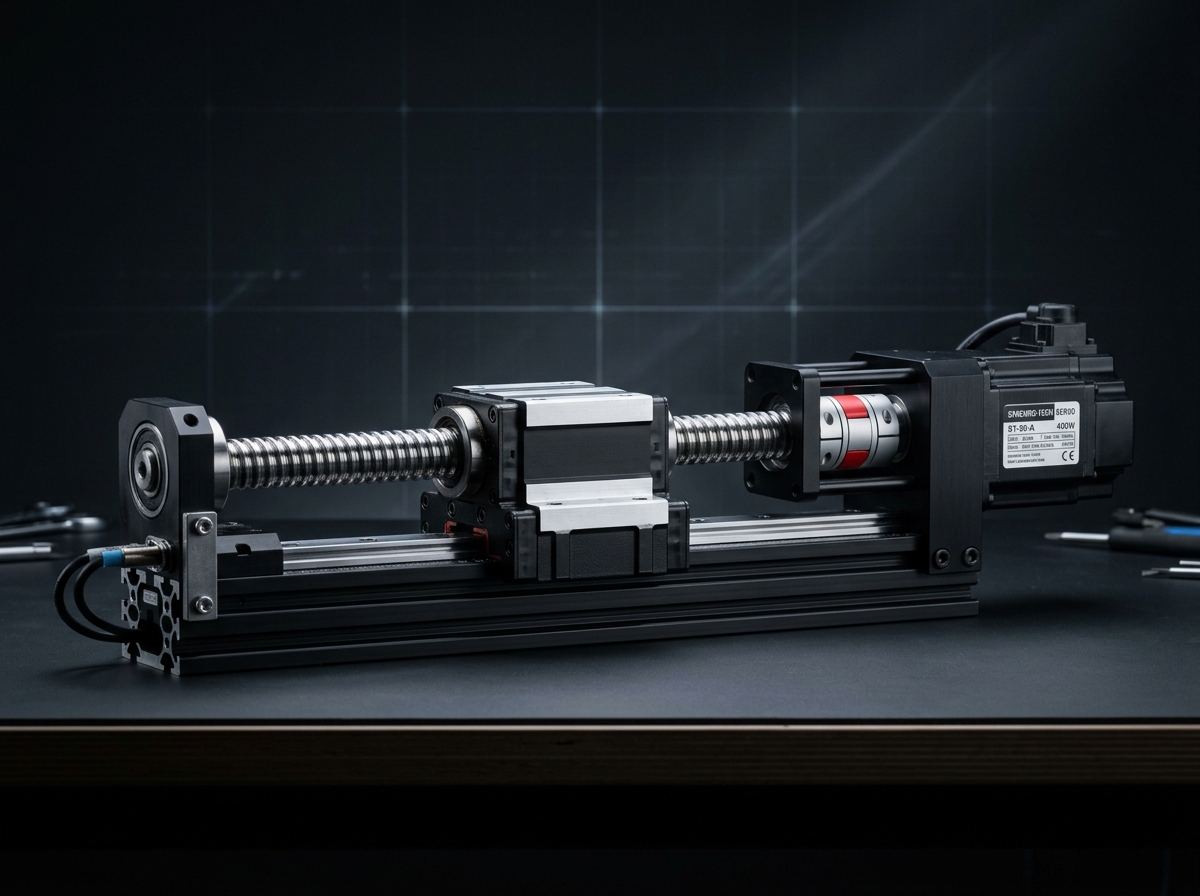
Precision guided linear motion module for controlled travel and repeatable positioning.
Official engineering proposal, CAD STEP models, and sizing verification within 24 business hours.
Detailed mechatronic breakdown of Linear Actuators, highlighting functional architecture, physical operating mechanisms, and deployment role.
The INDUS Intelligent Linear Actuator (IND-ILA series) replaces multi-component pneumatic and belt cylinders with a fully digitized, programmable electric linear drive. Operating directly on 48V DC, it integrates a high-precision rolled/ground C5 ball screw, dual recirculating ball rails, high-resolution optical scale, and on-board closed-loop vector controller.
The IND-ACT-LIN series converts rotary servomotor torque into rigid, highly guided linear displacement utilizing precision-ground C5 ball screws or steel-reinforced polyurethane synchronous belts. Dual recirculating ball linear guide rails provide high moment load absorption across horizontal and cantilevered stroke axes.
Addresses kinematic precision challenges by: Required stroke length including overtravel safety margins.
Serves as the high-precision torque-multiplication and motion-conversion core at robot joints, turntable positioners, and precision linear slides.
Packages brushless servomotor, zero-backlash harmonic reducer, dual absolute 19-bit optical encoders, and integrated 48V DC FOC drive into an IP65 mechatronic package.
16mm / 20mm screw diameter, 5mm, 10mm, or 20mm lead pitch
High mechanical efficiency (>90%) and rigid dynamic thrust transfer
Gothic arch profile with preloaded bearing blocks
High yaw, pitch, and roll moment load capacity across entire stroke
Direct inline or parallel fold-back coupling with synchronous belt
Zero backlash motor-to-screw drive transmission
1 µm resolution magnetic or optical readhead along extrusion
Eliminates thermal expansion error and mechanical backlash compensation
Real-time DSP drive vector telemetry, dual-encoder tracking error, and thermal equilibrium monitoring.
Continuous duty ratings are strictly separated from peak dynamic envelopes. All parameters reflect verified laboratory data traceable to INDUS Motion Lab ISO 230-2 Test Bench #4.
| Parameter | Specification Value | Unit | Notes & Test Conditions |
|---|---|---|---|
Continuous Rated Thrust Continuous | 050: 650 · 080: 1600 · 110: 3800 | N | At 25°C ambient, S1 duty cycle |
Max Acceleration Thrust Peak | 050: 1400 · 080: 3500 · 110: 7800 | N | Duration ≤ 0.5 sec |
Max Linear Speed Peak | 050: 1200 · 080: 1000 · 110: 800 | mm/s | Lead 20mm screw at 3000 rpm motor speed |
Repeatability (Bilateral) Nominal | 050: ±0.008 · 080: ±0.005 · 110: ±0.005 | mm | ISO 230-2 test standard with linear glass scale |
Effective Stroke Range Verified | 100 - 2500 | mm | Configurable in 50mm increments |
Continuous Thrust Force (Fx) Verified | 1250 | N | At 25°C ambient, continuous S1 duty cycle |
Peak Dynamic Thrust (Fx,max) Verified | 3100 | N | Duty cycle ≤ 10%, max duration 2.5s |
Maximum Linear Velocity Verified | 1.8 | m/s | With 20mm pitch ball screw at 5400 rpm input |
Bidirectional Repeatability Verified | ±0.010 | mm | At 20°C stabilized room temperature |
Lost Motion / Backlash Verified | 0.015 | mm | Preloaded zero-clearance double ball nut |
Permissible Pitch Moment (Mp) Verified | 285 | Nm | Dual runner block carriage |
Permissible Yaw Moment (My) Verified | 310 | Nm | Dual runner block carriage |
Permissible Roll Moment (Mr) Verified | 420 | Nm | Dual runner block carriage |
Select a verified physical variant below to inspect continuous ratings, peak torque/force envelopes, and dimension comparisons.
Every application below reflects documented load capabilities, thermal equilibrium boundaries, and kinematics integration for Linear Actuators.
Environment: Automotive Battery Cell Assembly (Dry room cleanroom environment, dew point -40°C).
Pneumatic cylinder air leaks, inconsistent press depths, and high compressed air energy consumption.
Closed-loop electric servo control with programmable thrust push mode guarantees uniform pressure without external load cells.
Environment: Electronics SMT & PCB Optical Inspection Line (Clean industrial room).
Belt stretch and vibration ringing causing settling delays and blurred camera frames at gantry inspection stations.
Rigid recirculating linear ball guides paired with 1 µm absolute optical scale eliminate mechanical stretch and achieve sub-millisecond settling.
Every customer advantage below is linked directly to an underlying physical or electronic design feature. Operating boundaries and verification conditions are explicitly declared.
Eliminates belt compliance and pneumatic compressibility, delivering rigid mechanical drive with >90% power efficiency.
Enables precise programmable position and thrust control with ±0.005mm bilateral repeatability.
Provides high dynamic yaw, pitch, and roll moment load resistance across strokes up to 1800mm.
Allows direct mounting of heavy tooling or grippers without requiring auxiliary external guide shafts.
Directly samples carriage linear position, bypassing screw thermal expansion and mechanical lead errors.
Guarantees sub-micron positioning accuracy in high-yield semiconductor and EV battery assembly.
Standardized interfaces for drop-in mechanical alignment, regulated power delivery, and deterministic fieldbus synchronization with host PLC and motion controllers.
NEMA 23 / 34 & IEC 60072-1 Metric Flange (60/80mm)
Mountable horizontally, vertically, or inverted. Vertical mounting requires motor brake.
48 VDC (Low Voltage) or 230/400 VAC (Servo Stage)
FOC servo drive with current, velocity, and position loop
Sync Cycle: 250 µs to 1 ms deterministic fieldbus cycle
Supports cyclic synchronized position (CSP), velocity (CSV), and torque (CST) operating modes.
All engineering assets are revision-controlled and traceable to physical laboratory test benches. Request calibrated files directly from our engineering desk without broken links.
IND-ILA-050-B10_ASSEMBLY.STEPAudited Lab Specification
Accurate C.G. Matrix
Official Documentation
High-torque rotary actuation module with zero-backlash gearing for joint articulation.
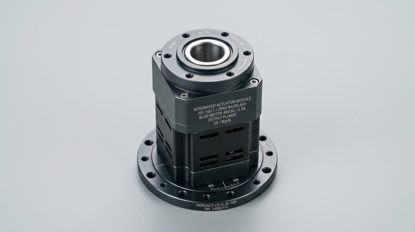
High-dynamic integrated servo module with built-in drive electronics and safety functions.
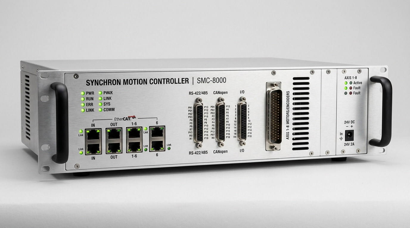
Centralized motion control engine synchronizing up to 64 coordinated axes over EtherCAT.
Direct answers to common engineering questions regarding sizing verification, mechanical tolerances, fieldbus integration, and documentation for Linear Actuators.
Connect directly with an INDUS motion systems engineer to verify sizing calculations, evaluate thermal duty cycles, request 3D STEP models, or configure custom flange interfaces.
• Official NDA protected technical evaluation
• 24 business hours standard proposal response
• Factory direct engineering support & CAD integration