Robotic Automation
Engineered-to-order industrial robotic cells, application kinematics, custom end-of-arm tooling, and certified ISO 10218 safety integration.
Turnkey articulated, SCARA, and collaborative robotic cells engineered for automated welding, machine tending, precision dispensing, and assembly.
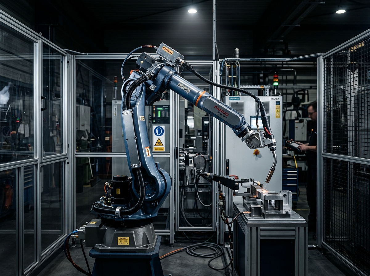
Robotic Automation package engineered with deterministic feedback loops, certified safety architecture, and full test logs.
The Industrial Robotic Challenge
Implementing robotic automation involves significant operational and technical risks. Sizing errors can lead to wrist motor overheating, unexpected cycle-time overruns, or joint singular regions where the robot cannot reach workpiece corners. Furthermore, complex part presentation and lack of robust safety zoning can compromise operator safety and cause chronic nuisance cell stoppages.
What The Solution Includes
We define clear engineering boundaries so plant managers and system integrators know exactly what INDUS designs, supplies, and commissions versus what requires plant facility hookup.
Engineered & Supplied by INDUS
Delivered fully tested and validated- Robotic manipulator selection (4-axis SCARA, 6-axis articulated, high-speed delta, cobot)
- Application-specific End-of-Arm Tooling (EOAT: electric servo, pneumatic, vacuum, magnetic)
- Industrial robot controller cabinet with safety teach pendant and remote I/O
- Cell fencing, interlocking safety gates, optical light curtains, and area scanners
- Master cell PLC integration and touch HMI with recipe and cycle diagnostics
- Offline simulation, 3D kinematic reach studies, and collision zone verification
Customer Plant Interfaces Required
Facility supplies and utility connections- →Level reinforced concrete foundation capable of absorbing dynamic robot overturning moments
- →Clean, dry pneumatic supply (6–8 bar, ISO 8573-1 Class 2:4:2) for pneumatic grippers
- →Primary electrical disconnect with plant emergency interlock interface
- →Incoming and outgoing part delivery conveyors or docking stations
Robotic Automation Architecture & Signal Flow
Part Presentation & Staging
Components enter the cell via indexed conveyors, vibratory trays, or pallet fixtures; optical sensors verify part readiness.
Verified Engineering Specifications
Performance parameters governed by international standards (ISO, IEC, DIN). Numerical values represent verified laboratory test benchmarks and require confirmation for specific workpiece payloads.
| Engineering Parameter | Benchmark Value | Governing Standard | Technical Qualification |
|---|---|---|---|
| Kinematic Repeatability | ±0.02 mm – ±0.05 mm | ISO 9283 (Manipulating Industrial Robots) | Verified across multi-axis dynamic trajectories under full rated payload. |
| Payload Capacity Range | 3 kg – 210 kg | Rated Wrist Flange Load | Accounts for tooling center of gravity (CoG) and dynamic inertial moment limits. |
| Working Reach Envelope | 400 mm – 3,100 mm | Spherical Geometric Radius | Extended reach options available with 7th-axis floor linear transfer track. |
| Safety Integrity Level | ISO 13849-1 Cat 4 PLe / SIL 3 | ISO 10218-1/2 & IEC 62061 | Hardware dual-channel monitored safety circuits with integrated STO and SLS. |
| Wrist Ingress Protection | IP65 / IP67 Washdown | IEC 60529 | Fully sealed wrist joints for harsh welding, casting, and machining environments. |
| Tool Flange Interface | ISO 9409-1-50 / 9409-1-100 | ISO 9409-1 Standard | Standardized mechanical bolt pattern and electrical slip-ring pass-through. |
Typical Applications & Use Cases
Representative production environments where this system configuration eliminates manual handling and improves takt pacing.
CNC machining center automated load and unload (machine tending)
Engineered with customized tool flanging, cycle interlocking, and dedicated safety boundaries.
Automotive robotic MIG/TIG and laser seam welding cells
Engineered with customized tool flanging, cycle interlocking, and dedicated safety boundaries.
Battery module precision sealant dispensing and screw fastening
Engineered with customized tool flanging, cycle interlocking, and dedicated safety boundaries.
Consumer electronics high-speed insertion and casing assembly
Engineered with customized tool flanging, cycle interlocking, and dedicated safety boundaries.
Metal casting deburring, grinding, and surface polishing
Engineered with customized tool flanging, cycle interlocking, and dedicated safety boundaries.
Plant Interfaces & Utility Requirements
Physical prerequisites required on the customer shop floor to enable rapid installation and commissioning.
400 VAC, 3-Phase + PE, 50/60 Hz (±10% allowable ripple)
Dedicated breaker recommended; 24 VDC / 20A redundant power for field sensors.
EtherCAT CoE or PROFINET IRT (Cat 6A shielded industrial Ethernet)
Deterministic master cycle rate ≤ 1.0 ms with distributed clocks enabled.
0.6 – 0.8 MPa (6 – 8 bar) clean dry air (ISO 8573-1:2010 Class 2:4:2)
Flow rate ≥ 150 NL/min with digital threshold interlock.
ISO 13849-1 Performance Level e (PLe) / Cat 4 compliant circuit
Dual-channel emergency stops, interlocked gates, and optional optical light curtains.
Testing, FAT & SAT Validation
Every system undergoes rigorous multi-phase verification before dispatch and after on-site installation.
3D Kinematic Simulation & Reach Freeze
Simulation of all robot poses, tool clearances, wrist singularity avoidance, and cable dress pack flex.
Zero singularities, minimum 100 mm safety clearance from all static frame members.
EOAT Grip Force & Dynamic Retention Audit
Testing gripper holding force under 2.5x maximum dynamic emergency stop deceleration forces.
Zero workpiece slippage; sensor verification of part presence across 500 consecutive cycles.
Factory Acceptance Testing (FAT)
Continuous 50-cycle pre-production run in INDUS integration facility with customer workpieces.
100% adherence to takt time, zero dropped parts, and complete safety interlock trip verification.
Site Acceptance Testing (SAT) & Handover
On-site installation, mechanical anchoring, laser leveling, utility hookup, and production ramp-up.
Customer sign-off on 8-hour continuous production run without unassisted cell stops.
Connected Product Ranges
Standard catalogue components verified for compatibility with this solution architecture.
Heavy Palletizing Cobot Arm (20kg Payload)
20 kg payload • 1,700 mm reach • ISO 10218-1 certified
High-Speed 4-Axis SCARA Manipulator
Payload 3-10 kg • Reach 400-800 mm • Cycle time < 0.35s
Multi-Axis Cartesian Linear Gantry Robot
Stroke up to 30,000 mm • Payloads 100-500 kg
6-Axis Robot Controller Cabinet with Teach Pendant
10.1" IPS Touchscreen • ISO 13849-1 Cat 4 / PLe
Frequently Asked Questions
Engineering specifics regarding lead times, PLC protocols, safety compliance, and commissioning.
Deploy Robotic Automation with Guaranteed FAT/SAT
Speak directly with our motion control application engineers for a detailed torque, inertia ratio, cycle takt simulation, and custom CAD space-claim envelope.
Explore Other Solution Packages
Smart Waste Collection Robot
An intelligent robotic waste collection system designed to identify, locate, and collect garbage automatically across urban, commercial, and campus environments.
Hospital Delivery Robot
An autonomous hospital delivery robot that transports medicines, medical supplies, documents and reports between hospital departments, reducing nurse workload and expediting pharmacy dispatch.
Agricultural Crop Monitoring Robot
An AI-powered agricultural robot that monitors crop health using cameras, sensors and computer vision, identifying early blight and pest threats across commercial greenhouses and open fields.