Motion Control
Sub-microsecond bus synchronization, dynamic trajectory generation, and closed-loop position control for high-speed automated machinery.
Coordinate multi-axis servo drives, frameless torque motors, and high-resolution absolute encoders into a unified deterministic motion subsystem.
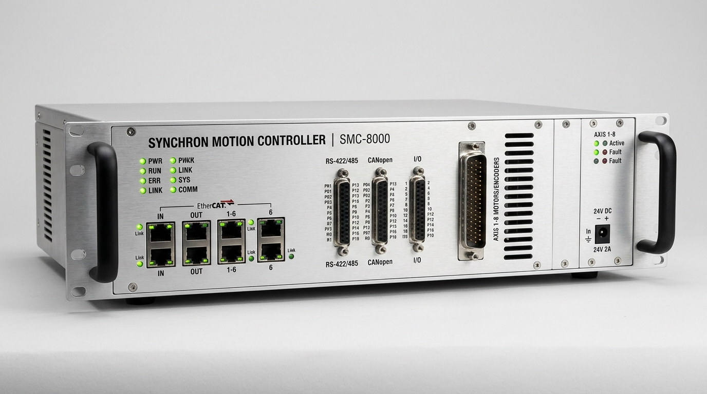
Motion Control package engineered with deterministic feedback loops, certified safety architecture, and full test logs.
The Industrial Motion Challenge
High-throughput packaging, CNC machining, and semiconductor assembly systems demand aggressive acceleration rates without introducing structural vibrations, contouring errors, or settling delays. When axes are loosely synchronized over non-deterministic networks, phase lag creates mechanical binding, surface finish ripple, and excessive component wear.
What The Solution Includes
We define clear engineering boundaries so plant managers and system integrators know exactly what INDUS designs, supplies, and commissions versus what requires plant facility hookup.
Engineered & Supplied by INDUS
Delivered fully tested and validated- Multi-axis master motion controllers (IPC / embedded DIN-rail)
- Digital servo amplifiers with dual-loop load feedback support
- Absolute optical and magnetic rotary/linear encoders (up to 24-bit)
- Zero-backlash strain-wave harmonic and planetary gearheads
- Deterministic fieldbus network master stacks (EtherCAT CoE / PROFINET IRT)
- Dynamic trajectory filters (S-curve jerk limiting, notch filtering, feedforward)
Customer Plant Interfaces Required
Facility supplies and utility connections- →Three-phase AC power feed (230 VAC / 400 VAC ±10%) with upstream breaker
- →Clean, low-noise earth ground with isolated shield grounding bar
- →Upstream line master PLC or supervisory SCADA communication interface
- →Physical space allocation in IP54/IP65 electrical control enclosure
Motion Control Architecture & Signal Flow
Trajectory Computation & Kinematics
Master motion IPC computes 3D path curves, jerk-limited velocity profiles, and axis transformation matrices every 250 µs.
Verified Engineering Specifications
Performance parameters governed by international standards (ISO, IEC, DIN). Numerical values represent verified laboratory test benchmarks and require confirmation for specific workpiece payloads.
| Engineering Parameter | Benchmark Value | Governing Standard | Technical Qualification |
|---|---|---|---|
| Fieldbus Synchronization Jitter | < 1.0 µs | IEC 61158 Type 12 (EtherCAT DC) | Verified across up to 32 synchronized drive nodes in cyclic synchronous mode. |
| Master Cycle Rate | 250 µs – 1.0 ms | CiA 402 Drive Profile | Configurable based on trajectory complexity and axis count. |
| Feedback Resolution | Up to 24-bit (16,777,216 counts/rev) | EnDat 2.2 / BiSS-C | Pure serial digital feedback immune to EMI noise over long cable runs. |
| Current Loop Frequency | 32 kHz (31.25 µs) | Field-Oriented Control (FOC) | Space-vector PWM switching with low acoustic motor noise. |
| Gear Backlash Threshold | < 0.1 arcmin (< 6 arcsec) | DIN 3990 / ISO 6336 | Zero lost motion achieved via flexspline harmonic gearing. |
| Functional Safety Rating | SIL 3 / Cat 4 PLe | IEC 61800-5-2 / ISO 13849-1 | Safe Torque Off (STO) hardwired dual-channel or FailSafe over EtherCAT (FSoE). |
Typical Applications & Use Cases
Representative production environments where this system configuration eliminates manual handling and improves takt pacing.
High-speed Cartesian pick-and-place gantries
Engineered with customized tool flanging, cycle interlocking, and dedicated safety boundaries.
Multi-axis CNC milling, grinding, and laser cutting heads
Engineered with customized tool flanging, cycle interlocking, and dedicated safety boundaries.
Electronic line shafting and continuous rotary printing
Engineered with customized tool flanging, cycle interlocking, and dedicated safety boundaries.
Semiconductor wafer inspection stages
Engineered with customized tool flanging, cycle interlocking, and dedicated safety boundaries.
Synchronized winding, tension control, and spooling machinery
Engineered with customized tool flanging, cycle interlocking, and dedicated safety boundaries.
Plant Interfaces & Utility Requirements
Physical prerequisites required on the customer shop floor to enable rapid installation and commissioning.
400 VAC, 3-Phase + PE, 50/60 Hz (±10% allowable ripple)
Dedicated breaker recommended; 24 VDC / 20A redundant power for field sensors.
EtherCAT CoE or PROFINET IRT (Cat 6A shielded industrial Ethernet)
Deterministic master cycle rate ≤ 1.0 ms with distributed clocks enabled.
0.6 – 0.8 MPa (6 – 8 bar) clean dry air (ISO 8573-1:2010 Class 2:4:2)
Flow rate ≥ 150 NL/min with digital threshold interlock.
ISO 13849-1 Performance Level e (PLe) / Cat 4 compliant circuit
Dual-channel emergency stops, interlocked gates, and optional optical light curtains.
Testing, FAT & SAT Validation
Every system undergoes rigorous multi-phase verification before dispatch and after on-site installation.
Frequency-Domain Resonance Identification
Chirp and step response excitation to identify mechanical anti-resonance and compliance frequencies.
Bode magnitude peaks identified; notch filters attenuating structural resonance by ≥ 18 dB.
Contour Error & Dynamic Tracking Audit
Laser interferometer and circular ballbar measurement during continuous 2D/3D interpolated motion.
Radial contouring deviation within agreed micron tolerance across full velocity range.
Thermal Drift & Continuous Duty Stress
Continuous 8-hour cyclic move profile measuring motor winding temperature and drivetrain growth.
Winding temperature rise under rated limits (ΔT < 60°C); thermal expansion mapped or compensated.
Factory Acceptance Testing (FAT)
Full-speed multi-axis cycle running customer-specified motion recipes with safety validation.
100% pass on STO trip time (< 20 ms), position repeatability, and continuous cycle completion.
Connected Product Ranges
Standard catalogue components verified for compatibility with this solution architecture.
64-Axis Deterministic EtherCAT Motion Controller
Up to 64 physical axes • 250 µs cycle • Intel Core i7
High-Performance IPC Robot Controller
Deterministic RT-Linux • Dual EtherCAT Masters • 24V DC
IND-PR-SW100 Cup Harmonic Reducer
Zero backlash • Ratios 50:1 to 160:1 • High torsional rigidity
IND-PR-RVE Solid-Output RV Reducer
Rated torque up to 3,200 Nm • High shock load capacity
Frequently Asked Questions
Engineering specifics regarding lead times, PLC protocols, safety compliance, and commissioning.
Deploy Motion Control with Guaranteed FAT/SAT
Speak directly with our motion control application engineers for a detailed torque, inertia ratio, cycle takt simulation, and custom CAD space-claim envelope.
Explore Other Solution Packages
Smart Waste Collection Robot
An intelligent robotic waste collection system designed to identify, locate, and collect garbage automatically across urban, commercial, and campus environments.
Hospital Delivery Robot
An autonomous hospital delivery robot that transports medicines, medical supplies, documents and reports between hospital departments, reducing nurse workload and expediting pharmacy dispatch.
Agricultural Crop Monitoring Robot
An AI-powered agricultural robot that monitors crop health using cameras, sensors and computer vision, identifying early blight and pest threats across commercial greenhouses and open fields.