Custom Engineering
Engineered-to-order robotic joint modules, custom actuation, specialized mechanical fixturing, and tailored OEM drivetrains.
Design, FEA simulation, prototyping, and turnkey manufacturing of custom robotic drivetrains and specialized automation hardware.
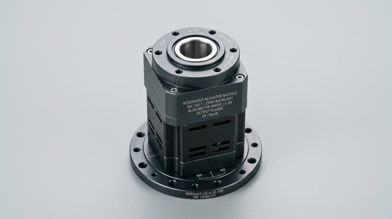
Custom Engineering package engineered with deterministic feedback loops, certified safety architecture, and full test logs.
The Custom Engineering Challenge
Off-the-shelf catalogue components are designed for general applications and often fail to satisfy extreme dimensional restrictions, unusual high-temperature or vacuum environments, or specialized weight constraints. Forcing catalogue hardware into tight OEM machines results in compromised payload capacity, overheating, inefficient power draw, and expensive packaging workarounds.
What The Solution Includes
We define clear engineering boundaries so plant managers and system integrators know exactly what INDUS designs, supplies, and commissions versus what requires plant facility hookup.
Engineered & Supplied by INDUS
Delivered fully tested and validated- Mechanical and electrical requirements discovery and kinematic feasibility analysis
- 3D CAD design, Finite Element Analysis (FEA) structural stiffness, and thermal dissipation modeling
- Engineered-to-order robotic joint modules (frameless motors + harmonic gearing + dual encoders)
- Custom end-of-arm tooling, vacuum manifolds, and specialized robotic fixtures
- Physical prototype machining, dynamic dynamometer testing, and environmental burn-in
- Comprehensive documentation: 3D STEP models, EPLAN schematics, BOM, and FAT/SAT test records
Customer Plant Interfaces Required
Facility supplies and utility connections- →Detailed CAD space envelope (STEP model) defining customer mounting boundaries and keep-out zones
- →Explicit operating duty cycle, continuous and peak torque/force envelopes, and life expectation
- →Customer electrical bus voltage, communication protocol preference, and connector pinouts
- →Customer sign-off on engineering milestone design reviews (PDR, CDR, and FAT protocols)
Custom Engineering Architecture & Signal Flow
Requirements Discovery & Boundary Definition
Analyze space claims, dynamic loading profiles, power constraints, and environmental requirements.
Verified Engineering Specifications
Performance parameters governed by international standards (ISO, IEC, DIN). Numerical values represent verified laboratory test benchmarks and require confirmation for specific workpiece payloads.
| Engineering Parameter | Benchmark Value | Governing Standard | Technical Qualification |
|---|---|---|---|
| Torque Density Ratio | Up to 120 Nm/kg | Optimized Hollow-Shaft Joint | Combines frameless torque motor and integrated harmonic gearing in lightweight housing. |
| FEA Structural Rigidity | < 5.0 µm Deflection under Load | Finite Element Analysis (FEA) | Verified at maximum dynamic rated overturning moment. |
| Operating Temperature Range | -40°C to +85°C (Custom Available) | Aerospace / Industrial Range | Specialized cryogenic, radiation-tolerant, and high-vacuum configurations on request. |
| Feedback Integration | Dual Absolute Encoders | BiSS-C / SSI Interface | Input motor speed feedback + output direct joint position feedback. |
| Bearing Arrangement | Integrated Preloaded Cross-Roller | High Moment Rigidity | Absorbs simultaneous radial, axial, and tilting moment loads. |
| Design Deliverables | Full STEP Models & Test Dossier | ISO 9001 Traceability | Complete manufacturing drawings, BOM, and individual test calibration reports. |
Typical Applications & Use Cases
Representative production environments where this system configuration eliminates manual handling and improves takt pacing.
Custom robotic arm joint actuators with integrated hollow bores for surgical tools
Engineered with customized tool flanging, cycle interlocking, and dedicated safety boundaries.
Specialized high-torque rotary indexers for downhole and subsea inspection tools
Engineered with customized tool flanging, cycle interlocking, and dedicated safety boundaries.
Compact motorized gimbal mounts for aerospace optical surveillance pods
Engineered with customized tool flanging, cycle interlocking, and dedicated safety boundaries.
Custom electric wheel drives for specialized AGV platforms with tight height constraints
Engineered with customized tool flanging, cycle interlocking, and dedicated safety boundaries.
Application-specific end effectors with tailored gripping fingers and embedded sensors
Engineered with customized tool flanging, cycle interlocking, and dedicated safety boundaries.
Plant Interfaces & Utility Requirements
Physical prerequisites required on the customer shop floor to enable rapid installation and commissioning.
400 VAC, 3-Phase + PE, 50/60 Hz (±10% allowable ripple)
Dedicated breaker recommended; 24 VDC / 20A redundant power for field sensors.
EtherCAT CoE or PROFINET IRT (Cat 6A shielded industrial Ethernet)
Deterministic master cycle rate ≤ 1.0 ms with distributed clocks enabled.
0.6 – 0.8 MPa (6 – 8 bar) clean dry air (ISO 8573-1:2010 Class 2:4:2)
Flow rate ≥ 150 NL/min with digital threshold interlock.
ISO 13849-1 Performance Level e (PLe) / Cat 4 compliant circuit
Dual-channel emergency stops, interlocked gates, and optional optical light curtains.
Testing, FAT & SAT Validation
Every system undergoes rigorous multi-phase verification before dispatch and after on-site installation.
Preliminary Design Review (PDR)
Presentation of concept kinematics, preliminary 3D models, FEA deflection, and torque calculations.
Customer engineering sign-off on space claim, electrical interfaces, and performance envelope.
Critical Design Review (CDR)
Final manufacturing drawings freeze, full thermal simulation, BOM lock, and component procurement release.
Customer freeze on all manufacturing drawings and agreed FAT test protocols.
Dynamometer & Functional Burn-In
Testing physical prototype on computer-controlled dynamometer test bench across full torque-speed curve.
Module delivers rated torque without exceeding thermal limits; continuous 24-hour burn-in verified.
Factory Acceptance Testing (FAT)
Customer witness testing of completed custom assembly checking dimensions, noise, and backlash.
Full compliance with agreed specification document and delivery of engineering dossier.
Connected Product Ranges
Standard catalogue components verified for compatibility with this solution architecture.
IND-PR-SW100 Cup Harmonic Reducer
Zero backlash • Customizable reduction ratios • High torque density
High-Performance IPC Robot Controller
Custom kinematics support • RT-Linux • Multiple fieldbuses
6-Axis Robot Controller Cabinet with Teach Pendant
Custom teach pendant software • Modular safety I/O
IND-PR-RVE Solid-Output RV Reducer
Heavy shock load resistance • Zero backlash
Frequently Asked Questions
Engineering specifics regarding lead times, PLC protocols, safety compliance, and commissioning.
Deploy Custom Engineering with Guaranteed FAT/SAT
Speak directly with our motion control application engineers for a detailed torque, inertia ratio, cycle takt simulation, and custom CAD space-claim envelope.
Explore Other Solution Packages
Smart Waste Collection Robot
An intelligent robotic waste collection system designed to identify, locate, and collect garbage automatically across urban, commercial, and campus environments.
Hospital Delivery Robot
An autonomous hospital delivery robot that transports medicines, medical supplies, documents and reports between hospital departments, reducing nurse workload and expediting pharmacy dispatch.
Agricultural Crop Monitoring Robot
An AI-powered agricultural robot that monitors crop health using cameras, sensors and computer vision, identifying early blight and pest threats across commercial greenhouses and open fields.