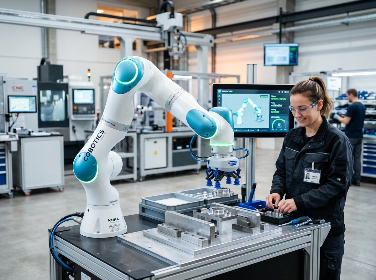
IND-ARM-COB-1000-C
Verified
Robotic Arms
Collaborative Robots
Safe, lightweight collaborative robot with intuitive hand-guided teaching and joint torque sensing.
Rated Wrist Payl…10.0 kg
Maximum Working …1300 mm
Pose Repeatability±0.030 mm
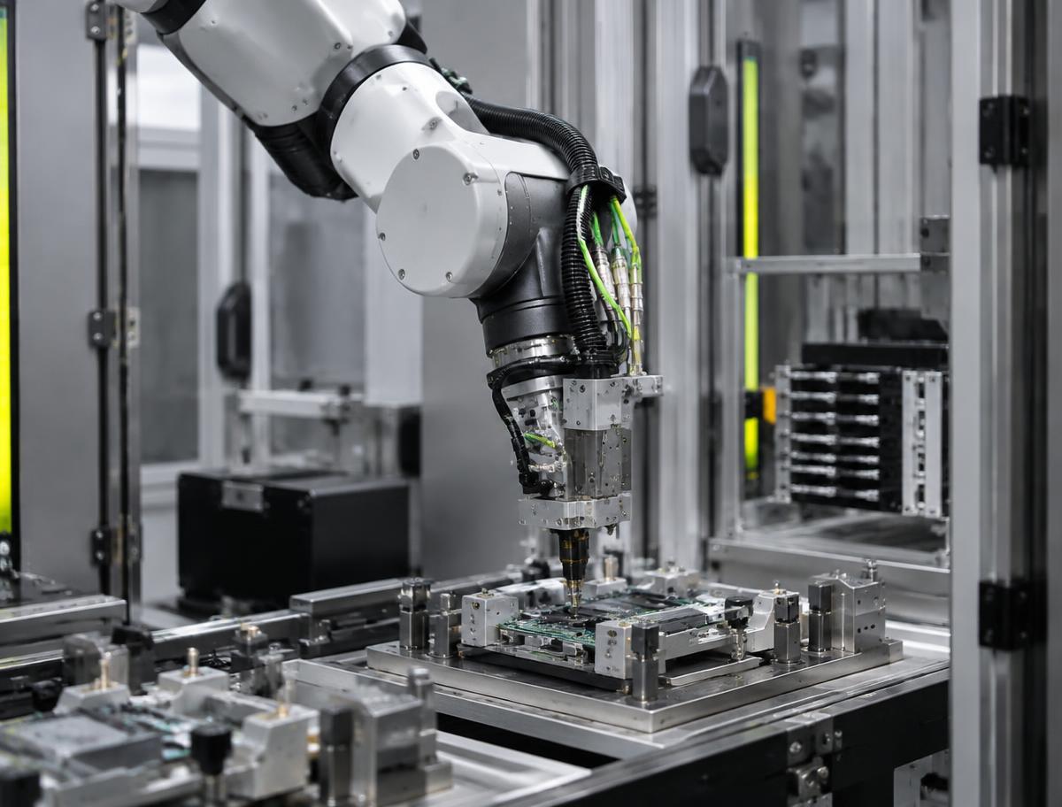
Flexible multi-axis platform for complex welding, machine tending, and precision assembly tasks.
Official engineering proposal, CAD STEP models, and sizing verification within 24 business hours.
Detailed mechatronic breakdown of 6-Axis Robots, highlighting functional architecture, physical operating mechanisms, and deployment role.
The IND-ARM-6AX-1400 is a versatile 6-axis articulated industrial robot engineered for precision material handling, machine tending, laser cutting, gluing, and automated deburring. Built with high-torque cycloidal base reducers and zero-backlash harmonic wrist stages, it combines a 1420mm spherical reach envelope with ISO 9283 pose repeatability within ±0.03mm.
The IND-ARM-6AX-1400 is a versatile 6-axis articulated industrial robot engineered for precision material handling, machine tending, laser cutting, gluing, and automated deburring. Built with high-torque cycloidal base reducers and zero-backlash harmonic wrist stages, it combines a 1420mm spherical reach envelope with ISO 9283 pose repeatability within ±0.03mm.
Addresses kinematic precision challenges by: Gripper mass + part mass: verify total payload is within wrist moment limit M_roll and M_pitch.
Executes high-speed multi-axis kinematic manipulation, assembly, welding, or material handling tasks within structured automated cells.
Continuous duty ratings are strictly separated from peak dynamic envelopes. All parameters reflect verified laboratory data traceable to INDUS Robotics Laser Tracker Metrology Facility (ISO 9283).
| Parameter | Specification Value | Unit | Notes & Test Conditions |
|---|---|---|---|
Rated Wrist Payload Verified | 12.0 | kg | Full reach and dynamic envelope |
Maximum Payload Capacity Verified | 15.0 | kg | With reduced wrist acceleration |
Maximum Spherical Reach Verified | 1420 | mm | From J1 center to J6 wrist flange face |
Pose Repeatability (RP) Verified | ±0.030 | mm | Measured across 30 points at full reach |
Path Repeatability (RT) Verified | ±0.050 | mm | Linear contouring at 500 mm/s |
Maximum TCP Velocity Verified | 2800 | mm/s | Full arm interpolation sweep |
Wrist Permissible Moment (M_roll) Verified | 38.5 | Nm | J4 / J5 wrist axis limit |
Wrist Permissible Moment (M_pitch) Verified | 38.5 | Nm | J5 / J6 axis limit |
Wrist Permissible Inertia Verified | 1.05 | kg·m² | Around J6 output flange axis |
Robot Manipulator Weight Verified | 145 | kg | Cast aluminum/iron arm structure |
Every application below reflects documented load capabilities, thermal equilibrium boundaries, and kinematics integration for 6-Axis Robots.
Environment: Industrial assembly, inspection, and robotic workcells
Eliminating cycle time bottlenecks and cumulative tolerance stack-up.
Integrates directly via standardized mechanical flanges and communication interfaces.
Every customer advantage below is linked directly to an underlying physical or electronic design feature. Operating boundaries and verification conditions are explicitly declared.
Eliminates dimensional variance and structural backlash across all production lots.
Guarantees drop-in mechanical interchangeability and repeatable kinematic trajectories.
Resists torsional and bending deflection under dynamic acceleration cycles.
Prevents machine vibration chatter and protects sensitive end-of-arm tooling.
Enables plug-and-play communication and rapid electrical integration.
Cuts system commissioning time by up to 50% and simplifies diagnostic tracing.
Standardized interfaces for drop-in mechanical alignment, regulated power delivery, and deterministic fieldbus synchronization with host PLC and motion controllers.
Robot Base Footprint (4-Bolt Circle Pattern)
Floor mount, wall mount, or ceiling (inverted) mount configured in controller
3-Phase 380-480 VAC, 50/60 Hz (3.5 kVA)
Multi-axis servo controller cabinet with regenerative resistor
Sync Cycle: 1 ms deterministic trajectory calculation
Supports cyclic synchronized position (CSP), velocity (CSV), and torque (CST) operating modes.
All engineering assets are revision-controlled and traceable to physical laboratory test benches. Request calibrated files directly from our engineering desk without broken links.
IND-6-AXIS_ASSEMBLY.STEPAudited Lab Specification
Accurate C.G. Matrix
Official Documentation
Safe, lightweight collaborative robot with intuitive hand-guided teaching and joint torque sensing.
Ruggedized articulated robot built for continuous 24/7 part transfer in demanding plants.
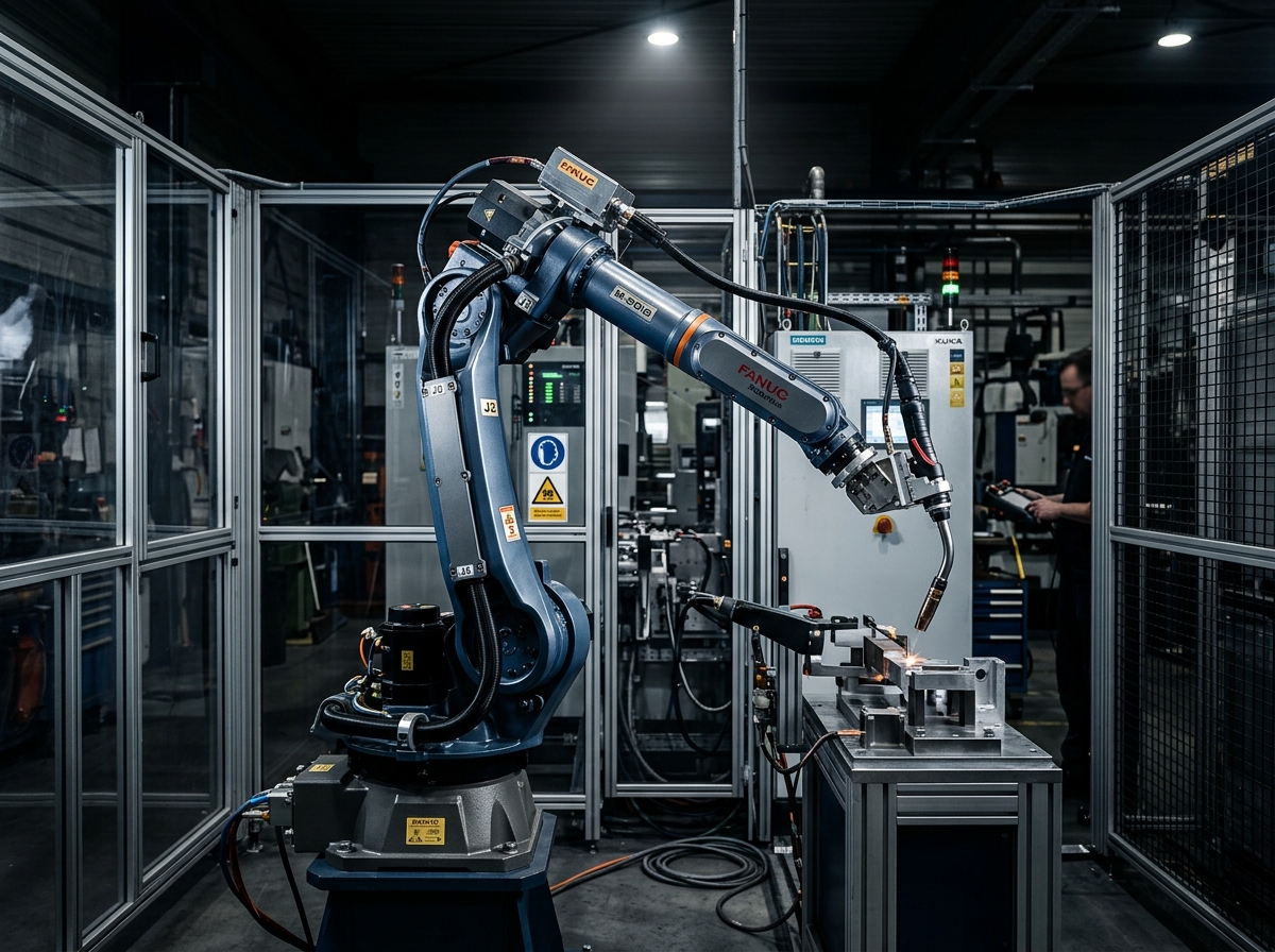
Hollow-wrist welding robot engineered for continuous MIG/MAG, TIG, and laser welding.
Direct answers to common engineering questions regarding sizing verification, mechanical tolerances, fieldbus integration, and documentation for 6-Axis Robots.
Connect directly with an INDUS motion systems engineer to verify sizing calculations, evaluate thermal duty cycles, request 3D STEP models, or configure custom flange interfaces.
• Official NDA protected technical evaluation
• 24 business hours standard proposal response
• Factory direct engineering support & CAD integration