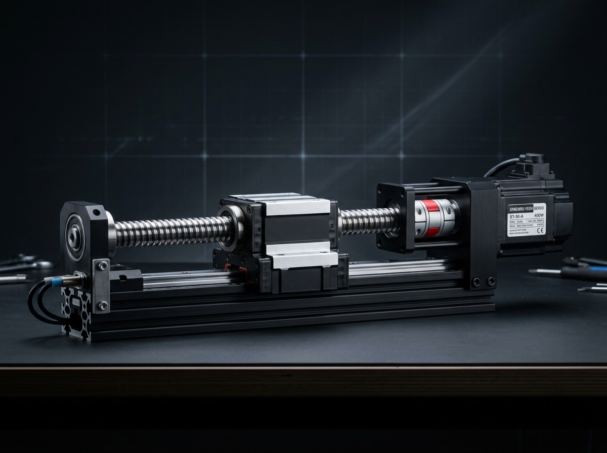
IND-ACT-LIN-200-B
Verified
Actuators
Linear Actuators
Precision guided linear motion module for controlled travel and repeatable positioning.
Effective Stroke…100 - 2500 mm
Continuous Thrus…1250 N
Peak Dynamic Thr…3100 N
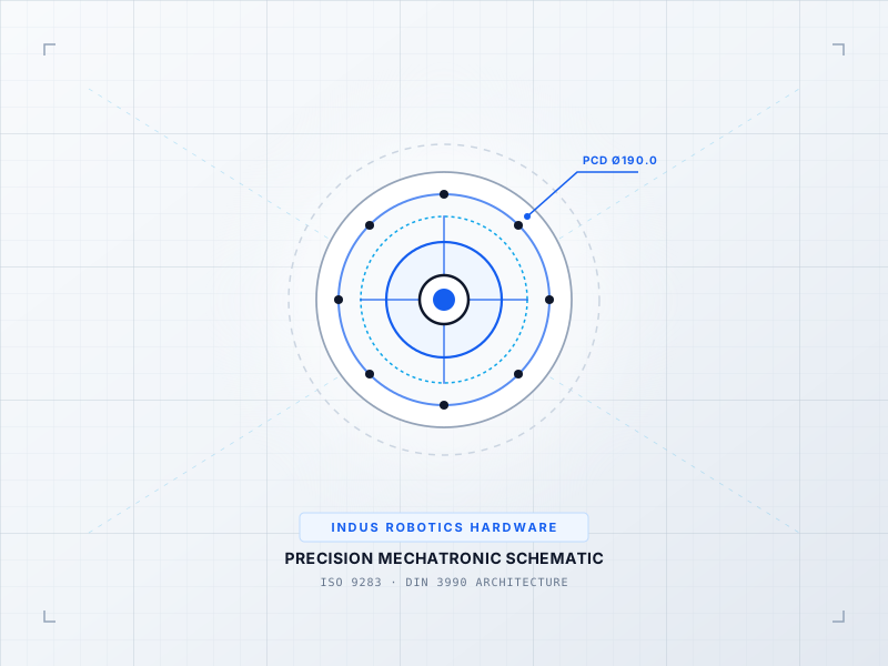
High-torque 90-degree right angle spiral bevel transmission with ground gears.
Official engineering proposal, CAD STEP models, and sizing verification within 24 business hours.
Detailed mechatronic breakdown of RAB-115 Right-Angle Spiral Bevel Gearbox, highlighting functional architecture, physical operating mechanisms, and deployment role.
Right-angle precision hypoid bevel gearbox providing high continuous torque redirection in compact spatial envelopes for conveyor transfer corners and robot peripheral tooling.
Precision case-hardened spiral bevel gear set operating with lapped tooth profiles for smooth 90-degree vector torque distribution.
Solves multi-axis alignment errors, mechanical backlash drift, and dynamic vibration during high-speed production cycles.
Serves as the high-precision torque-multiplication and motion-conversion core at robot joints, turntable positioners, and precision linear slides.
Kinematic speed reduction and torque multiplication via elastic flexspline deformation or multi-pin cycloidal eccentricity. Assigned to Robot Joint Articulation (J1 through J6) & Rotary Positioning Stages.
Motor input shaft delivers high rotational velocity (2,000 - 6,000 RPM) with low mechanical torque to the reducer input hub.
Input assembly continuously deflects flexible or cycloidal gear elements, causing simultaneous conjugate meshing across 30%+ of teeth without backlash.
Output cross-roller bearing delivers high continuous torque (Tau_out = Tau_in * ratio * efficiency) with sub-arcminute lost motion.
Zero mechanical backlash but requires significantly larger motor volume, higher continuous power, and active cooling to achieve equivalent joint torque.
Higher mechanical efficiency and shock capacity, but exhibits 1-3 arcmin backlash compared to true zero-backlash strain-wave units.
Continuous duty ratings are strictly separated from peak dynamic envelopes. All parameters reflect verified laboratory data traceable to ISO 9283 / IEC 60034 Industrial Automation Standard.
| Parameter | Specification Value | Unit | Notes & Test Conditions |
|---|---|---|---|
Nominal Torque Verified | 280 Nm | Nm | Confirmed upon order specification review. |
Gear Ratio Verified | 5:1 | — | Confirmed upon order specification review. |
Backlash Verified | < 6 arcmin | arcmin | Confirmed upon order specification review. |
Input Speed Verified | 3,000 RPM | rpm | Confirmed upon order specification review. |
Efficiency Verified | ≥ 95% | % | Confirmed upon order specification review. |
Housing Material Verified | High-Tensile Ductile Iron | N | Confirmed upon order specification review. |
Every application below reflects documented load capabilities, thermal equilibrium boundaries, and kinematics integration for RAB-115 Right-Angle Spiral Bevel Gearbox.
Environment: Industrial assembly, inspection, and robotic workcells
Eliminating cycle time bottlenecks and cumulative tolerance stack-up.
Integrates directly via standardized mechanical flanges and communication interfaces.
Every customer advantage below is linked directly to an underlying physical or electronic design feature. Operating boundaries and verification conditions are explicitly declared.
Eliminates dimensional variance and structural backlash across all production lots.
Guarantees drop-in mechanical interchangeability and repeatable kinematic trajectories.
Resists torsional and bending deflection under dynamic acceleration cycles.
Prevents machine vibration chatter and protects sensitive end-of-arm tooling.
Enables plug-and-play communication and rapid electrical integration.
Cuts system commissioning time by up to 50% and simplifies diagnostic tracing.
Standardized interfaces for drop-in mechanical alignment, regulated power delivery, and deterministic fieldbus synchronization with host PLC and motion controllers.
ISO Standard Flange / Precision Dowel Alignment
Universal mounting in horizontal, vertical, or inverted orientations with precision dowel hole alignment.
48V DC Regulated Bus (24V–56V range)
Integrated field-oriented control or compatible with standard industrial AC/DC servo inverters.
Cycle Time ≤ 1.0 ms (Jitter < 1 µs)
Supports cyclic synchronized position (CSP), velocity (CSV), and torque (CST) operating modes.
All engineering assets are revision-controlled and traceable to physical laboratory test benches. Request calibrated files directly from our engineering desk without broken links.
IND-RED-RAB-115_ASSEMBLY.STEPAudited Lab Specification
Accurate C.G. Matrix
Official Documentation
Precision guided linear motion module for controlled travel and repeatable positioning.
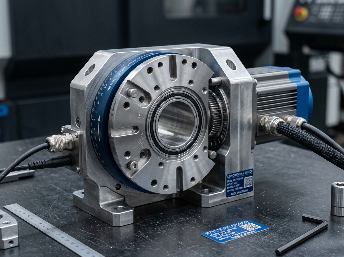
High-torque rotary actuation module with zero-backlash gearing for joint articulation.
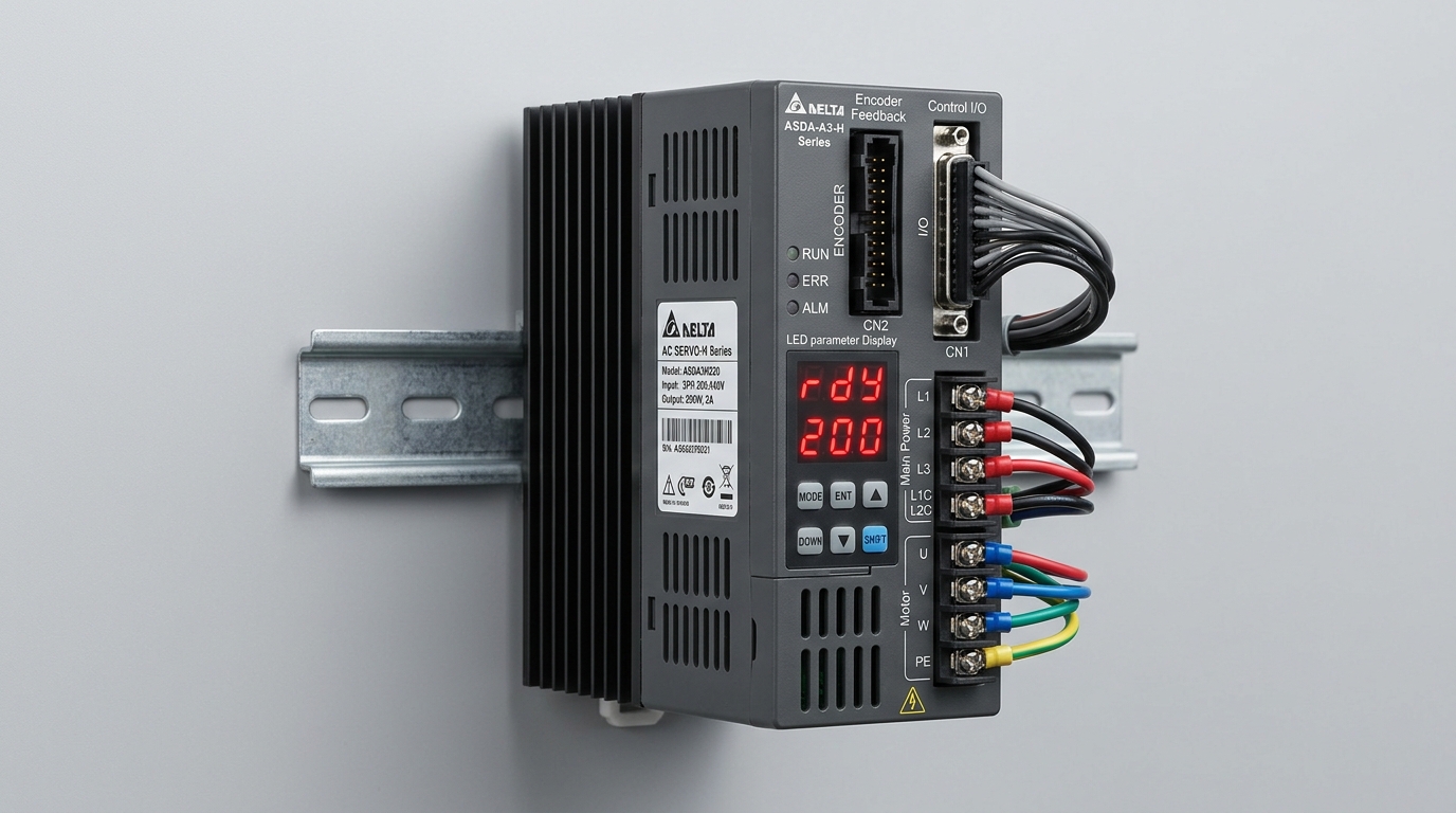
Compact multi-axis digital servo amplifier regulating current, velocity, and position loops.
Direct answers to common engineering questions regarding sizing verification, mechanical tolerances, fieldbus integration, and documentation for RAB-115 Right-Angle Spiral Bevel Gearbox.
Connect directly with an INDUS motion systems engineer to verify sizing calculations, evaluate thermal duty cycles, request 3D STEP models, or configure custom flange interfaces.
• Official NDA protected technical evaluation
• 24 business hours standard proposal response
• Factory direct engineering support & CAD integration