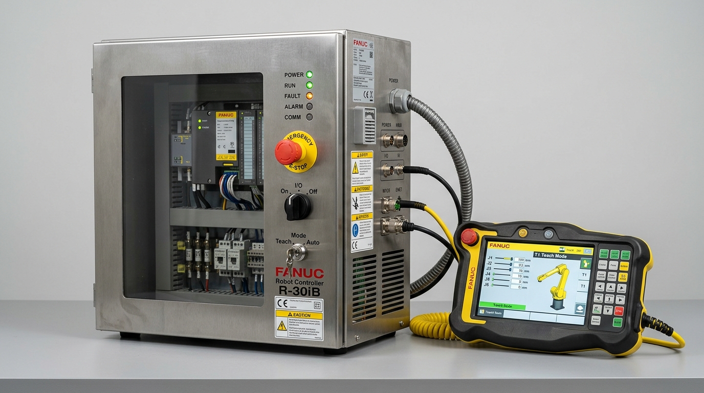
IND-CTL-RBC-X86-RT
Verified
Control Systems
Robot Controllers
Industrial-grade controller computing forward/inverse kinematics with integrated functional safety.
Coordinated Axis…Up to 16 Axes axes
Trajectory Inter…1.0 ms
EtherCAT Master …< 1.0 µs
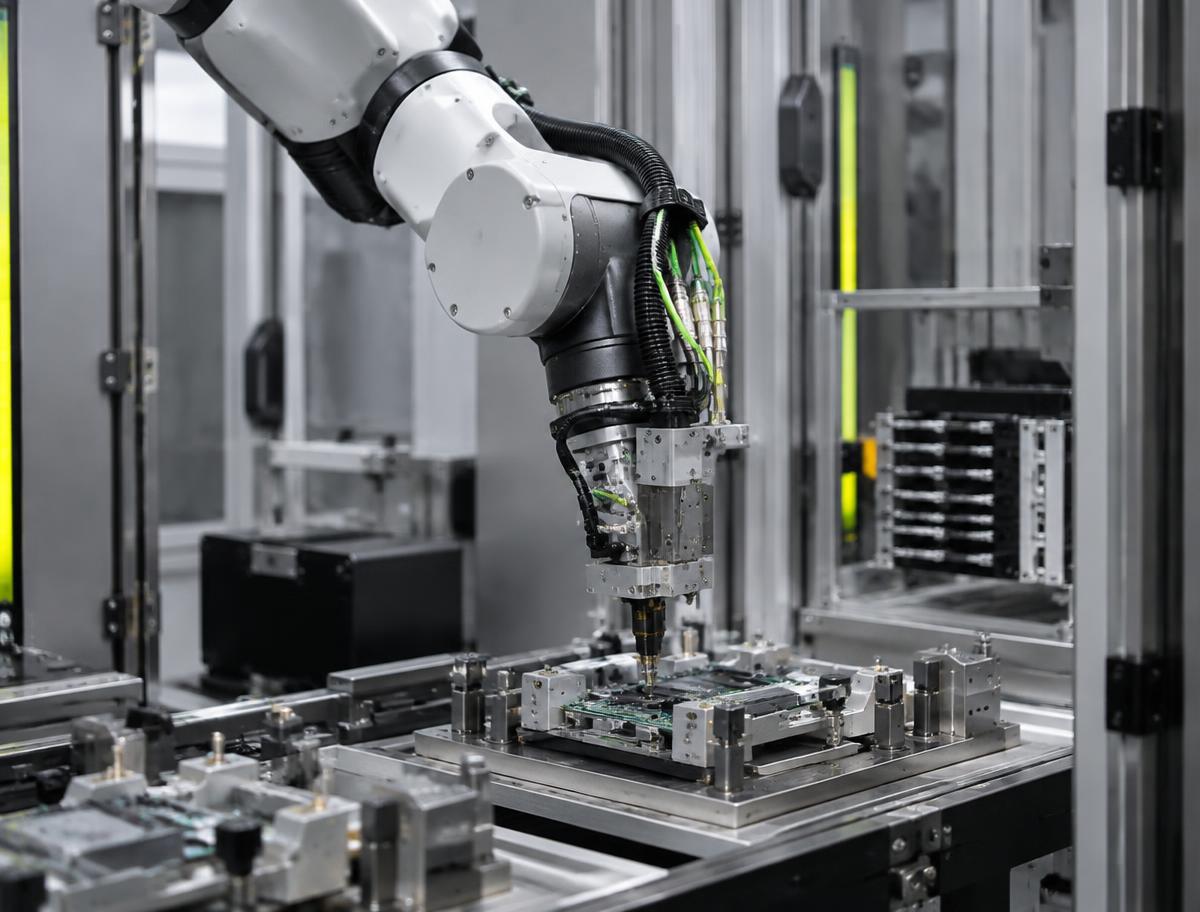
Extreme payload handling in harsh foundry casting, forging press, and heavy stamping transfer environments.
Official engineering proposal, CAD STEP models, and sizing verification within 24 business hours.
Detailed mechatronic breakdown of Heavy-Duty Foundry & Stamping 6-Axis Arm (50–250kg), highlighting functional architecture, physical operating mechanisms, and deployment role.
Extreme payload handling in harsh foundry casting, forging press, and heavy stamping transfer environments.
High-rigidity RV cycloidal drives on primary axes with pressurized IP67 wrist cavities resistant to foundry heat and scale.
Eliminates operational failure modes related to: Payload capacity (50 - 250 kg), Wrist IP rating (IP67 foundry coat).
Executes high-speed multi-axis kinematic manipulation, assembly, welding, or material handling tasks within structured automated cells.
Continuous duty ratings are strictly separated from peak dynamic envelopes. All parameters reflect verified laboratory data traceable to ISO 10218-1 / ISO 10218-2 / ISO/TS 15066.
| Parameter | Specification Value | Unit | Notes & Test Conditions |
|---|---|---|---|
Payload Verified | 50 - 250 kg | kg | Audited per Harsh Environment Robotics Ingress Protocol IEC 60529 |
Reach Verified | 2,050 - 2,700 mm | mm | Audited per Harsh Environment Robotics Ingress Protocol IEC 60529 |
Protection Verified | IP67 Foundry Plus | µs | Audited per Harsh Environment Robotics Ingress Protocol IEC 60529 |
Wrist Torque Verified | Up to 1,450 Nm | Nm | Audited per Harsh Environment Robotics Ingress Protocol IEC 60529 |
System Interface Compatibility Standard | ISO 9409-1-125-6-M10 flange; High-power 400V AC servo cabinet | Standard | Supported physical and electronic mating connections |
Select a verified physical variant below to inspect continuous ratings, peak torque/force envelopes, and dimension comparisons.
Every application below reflects documented load capabilities, thermal equilibrium boundaries, and kinematics integration for Heavy-Duty Foundry & Stamping 6-Axis Arm (50–250kg).
Environment: Automated production facilities and manufacturing cells
Demanding precision positioning and repeatability requirements under high-duty continuous operation.
Provides calibrated Heavy-Duty Foundry & Stamping 6-Axis Arm (50–250kg) performance adhering strictly to ISO 10218-1 / ISO 10218-2 / ISO/TS 15066.
Environment: Automated production facilities and manufacturing cells
Demanding precision positioning and repeatability requirements under high-duty continuous operation.
Provides calibrated Heavy-Duty Foundry & Stamping 6-Axis Arm (50–250kg) performance adhering strictly to ISO 10218-1 / ISO 10218-2 / ISO/TS 15066.
Environment: Automated production facilities and manufacturing cells
Demanding precision positioning and repeatability requirements under high-duty continuous operation.
Provides calibrated Heavy-Duty Foundry & Stamping 6-Axis Arm (50–250kg) performance adhering strictly to ISO 10218-1 / ISO 10218-2 / ISO/TS 15066.
Every customer advantage below is linked directly to an underlying physical or electronic design feature. Operating boundaries and verification conditions are explicitly declared.
Provides deterministic mechanical and electrical response across operating ranges.
Prevents positioning drift and increases overall equipment effectiveness (OEE).
Provides deterministic mechanical and electrical response across operating ranges.
Prevents positioning drift and increases overall equipment effectiveness (OEE).
Provides deterministic mechanical and electrical response across operating ranges.
Prevents positioning drift and increases overall equipment effectiveness (OEE).
Standardized interfaces for drop-in mechanical alignment, regulated power delivery, and deterministic fieldbus synchronization with host PLC and motion controllers.
ISO 9409-1-125-6-M10 flange
Universal mounting in horizontal, vertical, or inverted orientations with precision dowel hole alignment.
48V DC Regulated Bus (24V–56V range)
Integrated field-oriented control or compatible with standard industrial AC/DC servo inverters.
Cycle Time ≤ 1.0 ms (Jitter < 1 µs)
Supports cyclic synchronized position (CSP), velocity (CSV), and torque (CST) operating modes.
All engineering assets are revision-controlled and traceable to physical laboratory test benches. Request calibrated files directly from our engineering desk without broken links.
IND-ROB-HEAVY-FOUNDRY_ASSEMBLY.STEPAudited Lab Specification
Accurate C.G. Matrix
Official Documentation
Industrial-grade controller computing forward/inverse kinematics with integrated functional safety.
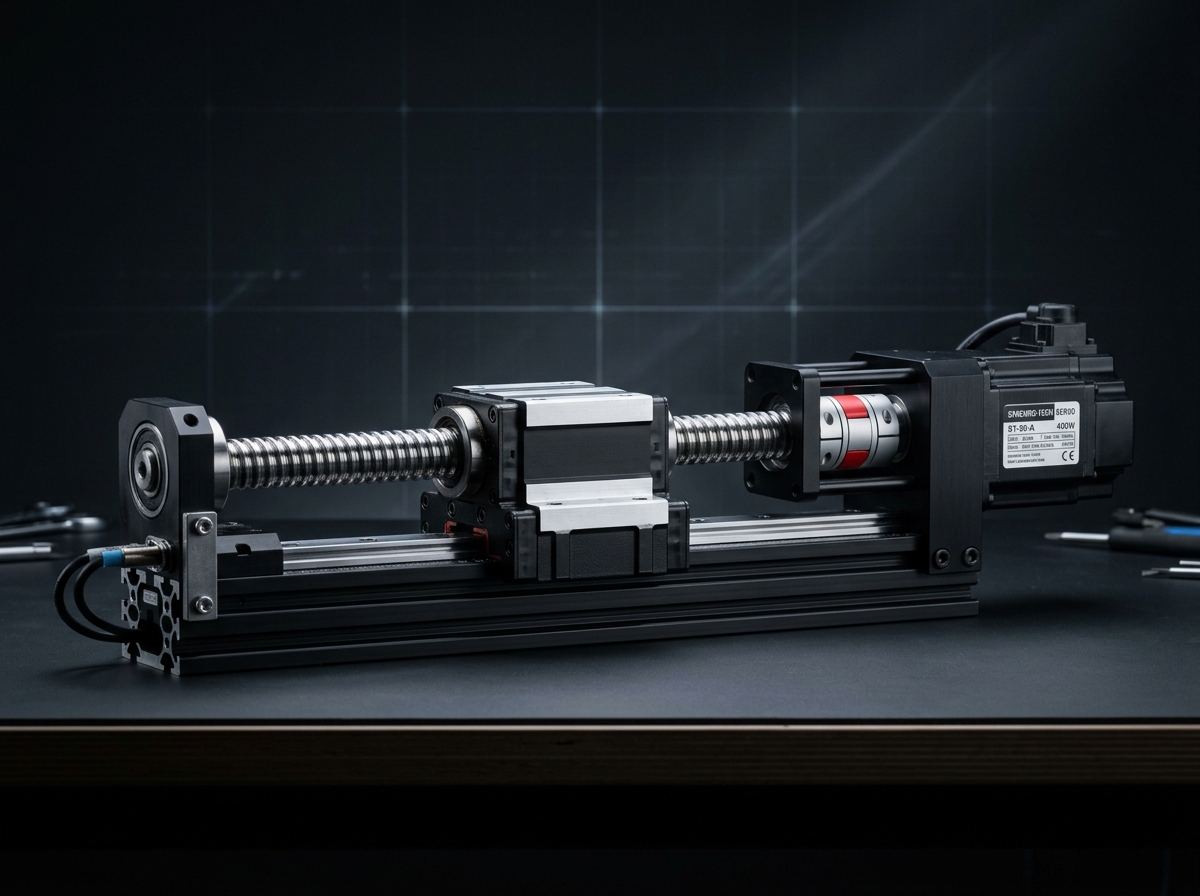
Precision guided linear motion module for controlled travel and repeatable positioning.
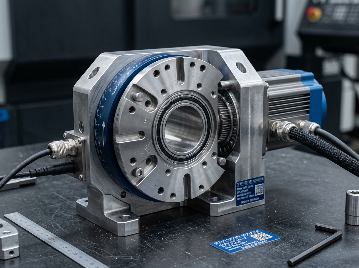
High-torque rotary actuation module with zero-backlash gearing for joint articulation.
Direct answers to common engineering questions regarding sizing verification, mechanical tolerances, fieldbus integration, and documentation for Heavy-Duty Foundry & Stamping 6-Axis Arm (50–250kg).
Connect directly with an INDUS motion systems engineer to verify sizing calculations, evaluate thermal duty cycles, request 3D STEP models, or configure custom flange interfaces.
• Official NDA protected technical evaluation
• 24 business hours standard proposal response
• Factory direct engineering support & CAD integration