INDUS
Precision Motion & Automation
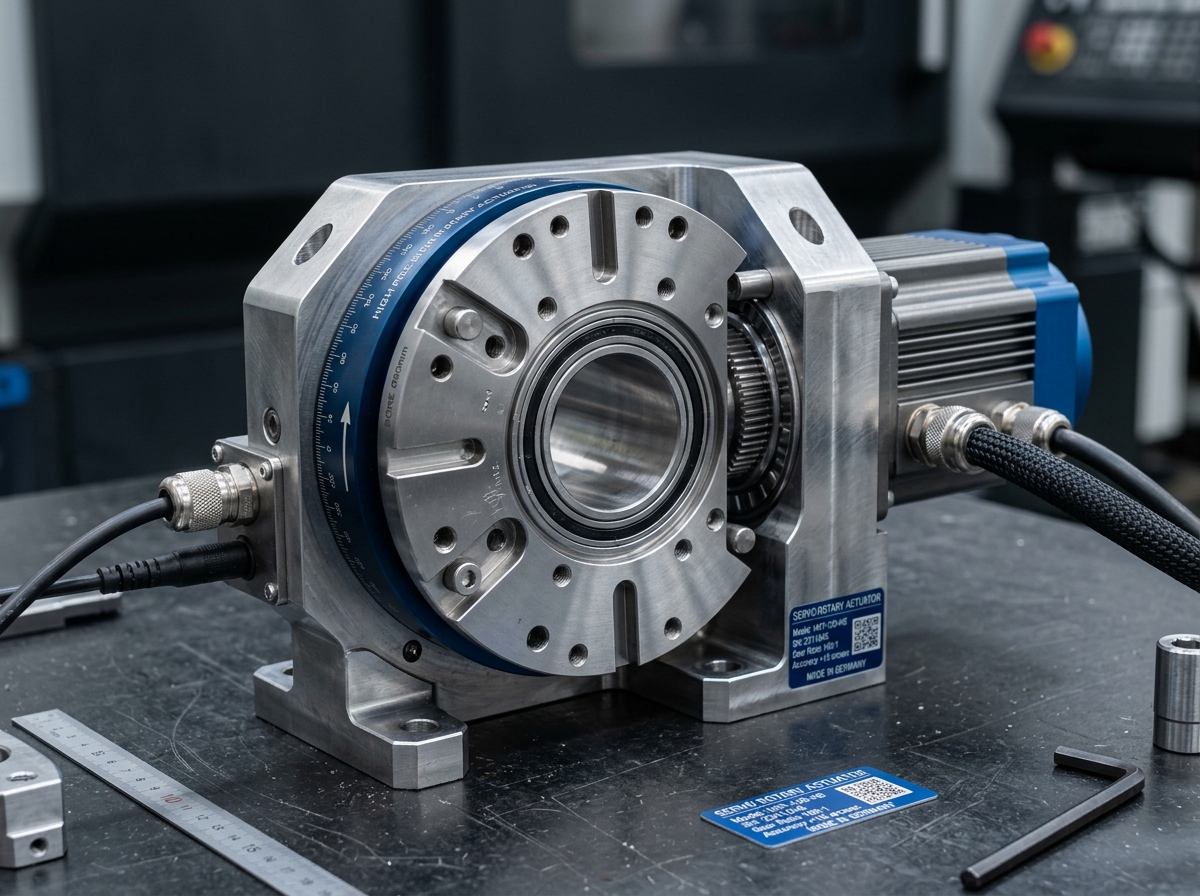
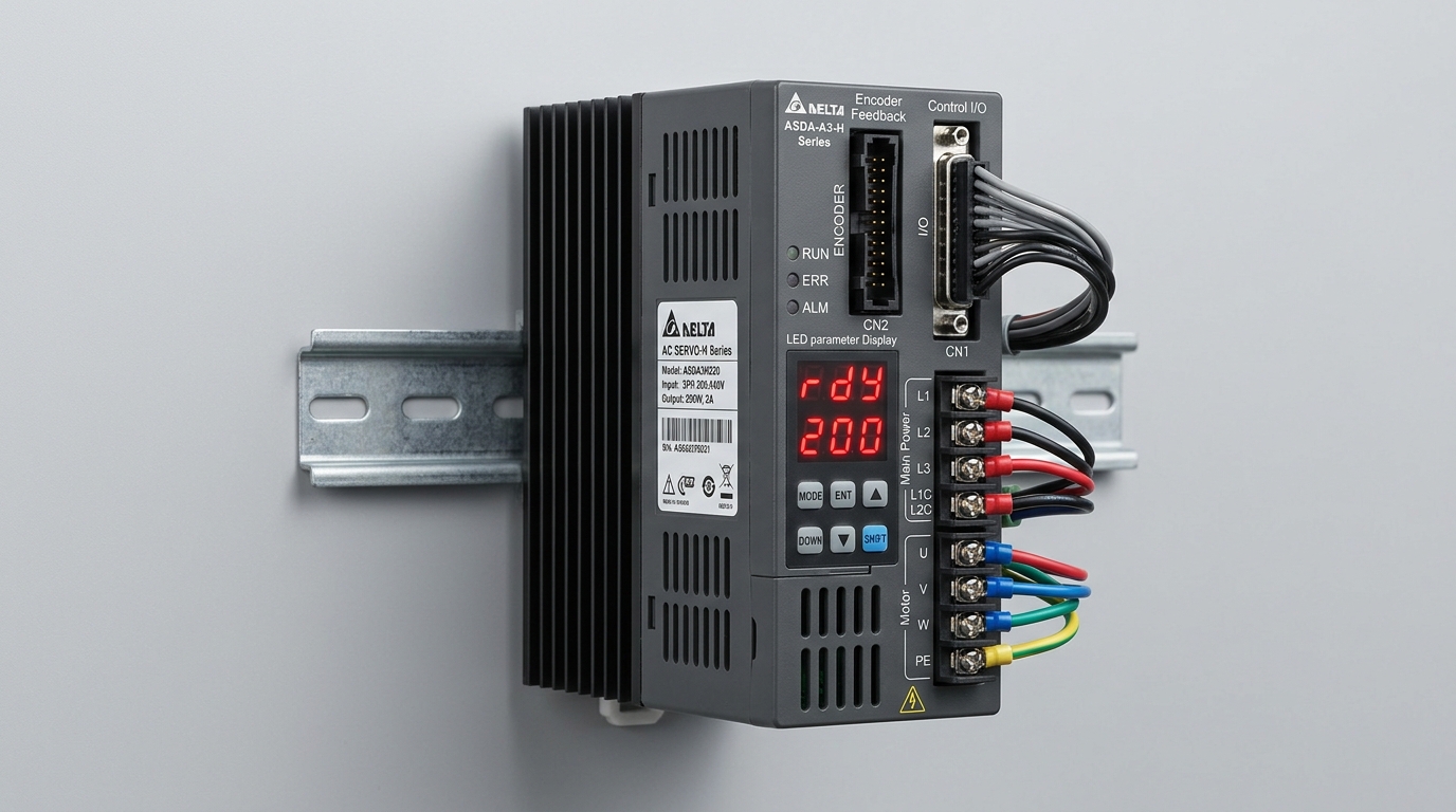
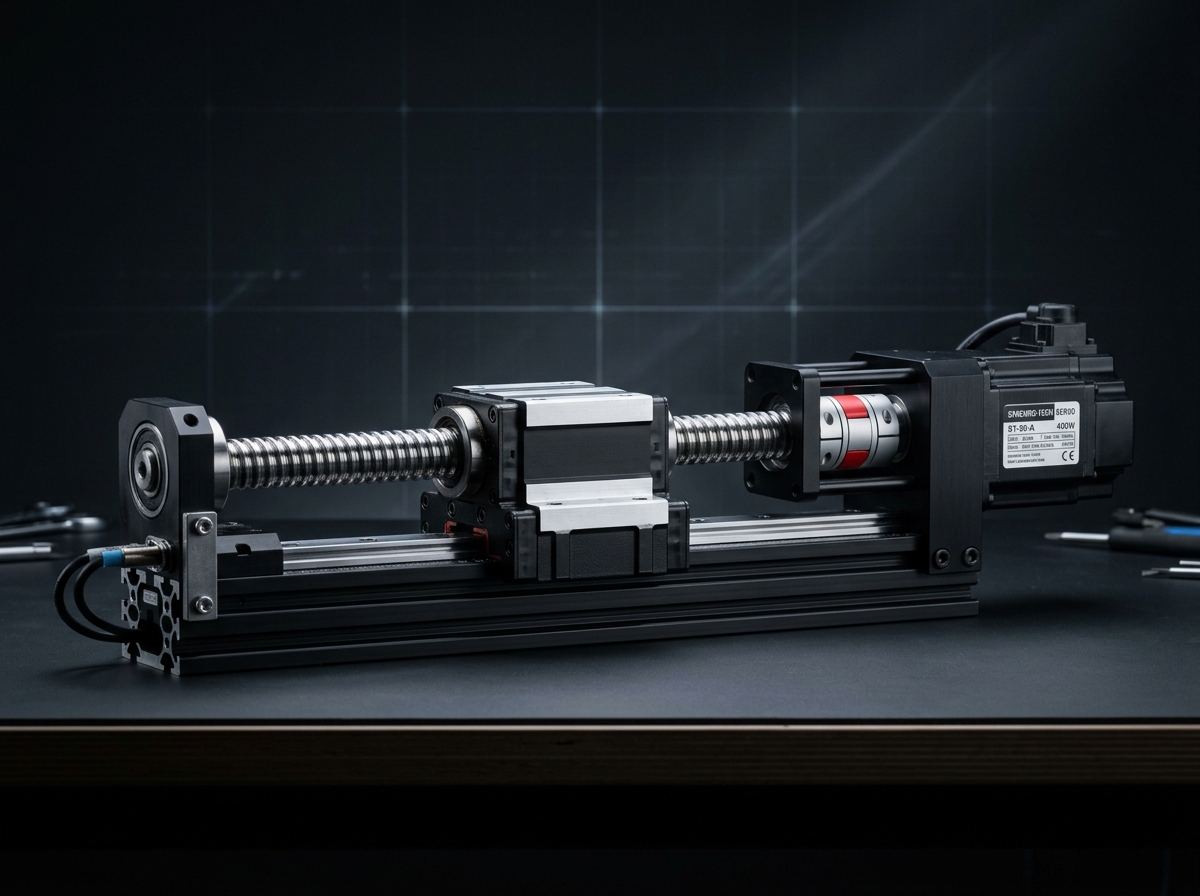
ASD-48 Dual-Axis Low-Latency Digital AC Servo Drive (IND-DRV-ASD48) technical hardware illustration
Model Identifier:IND-DRV-ASD48
Engineering Standard:ISO 9283
Verification Level: Audited Specification
Traceable Lab Bench TestingView Full Matrix ↓
Servo Drives and Motor Drives/Servo Drives and Motor Drives

ASD-48 Dual-Axis Low-Latency Digital AC Servo Drive

Dual-axis EtherCAT servo amplifier with 3.2 kHz frequency response and STO SIL3.

Output Current25 A Peak / 12 A Continuous per AxisStandard specification
Input Voltage3-Phase 200-240 VAC or 48-80 VDC OptionStandard specification
Current Loop Bandwidth3.2 kHzStandard specification
Velocity Loop Bandwidth1.2 kHzStandard specification
Inventory & Batch AllocationConfigurable Order Quantity (Min 1 · Max 16 Units)
Lead Time: 1-2 Weeks
50 available in stockOrder limits: Min 1 · Max 16 units

Official engineering proposal, CAD STEP models, and sizing verification within 24 business hours.

3. Product Overview & Operating Principle

Engineering Fundamentals & Automation Architecture

Detailed mechatronic breakdown of ASD-48 Dual-Axis Low-Latency Digital AC Servo Drive, highlighting functional architecture, physical operating mechanisms, and deployment role.

1. What the Product Is

Dual-axis space-saving digital servo amplifier featuring 3.2 kHz current loop bandwidth, auto-tuning notch filters, and hardware Safe Torque Off (STO SIL3).

2. Operating Physical Principle

Field-oriented space vector PWM control (FOC) commutates AC brushless and PMSM servomotors with low current ripple and optimal thermal efficiency.

3. Engineering Problem Addressed

Solves multi-axis alignment errors, mechanical backlash drift, and dynamic vibration during high-speed production cycles.

4. Role in Automation Systems

Acts as the central deterministic computing core or power amplifier, executing multi-axis motion trajectories and real-time fieldbus synchronization.

Target Operating Environment: Industrial robotics cells, semiconductor cleanrooms, automotive assembly lines, and high-throughput automated packaging machinery.
Physics & Mechatronic Operating Principle

Kinematic Transformation Sequence for ASD-48 Dual-Axis Low-Latency Digital AC Servo Drive

High-bandwidth cascaded closed-loop control (Current, Velocity, Position) with Wide-Bandgap (SiC/GaN) inverter modulation. Assigned to Power Conversion, Dynamic Motor Regulation & Functional Safe Torque Off.

STEP 01Kinematic Phase

Fieldbus Setpoint Latching

Drive receives target position and velocity feedforward from motion controller over EtherCAT / PROFINET IRT.

Input State:Cyclic target position telegram + timing sync pulse
Physical Transformation:Position loop comparator calculating position error: e_pos = target_pos - actual_pos
Output State:Target velocity command to velocity loop filter
STEP 02Kinematic Phase

Cascaded Velocity & Current Regulation

PI velocity controller and high-frequency Field-Oriented Current loop (10-20 kHz) calculate required stator voltage vectors.

Input State:Velocity error + phase current shunt/Hall feedback
Physical Transformation:Clark/Park dq-axis transformations and active anti-resonance notch filtering
Output State:Space Vector PWM gating duty cycles (Vd, Vq)
STEP 03Kinematic Phase

Inverter Power Stage Modulation

Silicon Carbide (SiC) MOSFET bridge switches DC bus voltage into high-current 3-phase motor windings with minimal thermal loss.

Input State:PWM gate driver signals (dead-time compensated)
Physical Transformation:Solid-state bridge switching modulated 400V/48V 3-phase power
Output State:Calibrated motor phase currents driving joint rotation
Diagnostic Quality Checkpoints
  • [1]Current loop bandwidth (-3dB cutoff frequency > 2.5 kHz)
  • [2]DC bus voltage ripple under regenerative braking deceleration
  • [3]Dual-channel Safe Torque Off (STO) diagnostic integrity
Alternative Technologies & Engineering Trade-Offs

Variable Frequency Drives (VFD)

Economical for open-loop induction motor pump/fan speed control, but cannot achieve the microsecond dynamic positioning needed for robotics.

Analog Servo Amplifiers

Zero digital processing latency, but suffers from thermal drift, lack of fieldbus telemetry, and cannot store multi-axis digital filter parameters.

4. Verified Technical Specifications

Engineering Specification Matrix

Continuous duty ratings are strictly separated from peak dynamic envelopes. All parameters reflect verified laboratory data traceable to ISO 9283 / IEC 60034 Industrial Automation Standard.

ParameterSpecification ValueUnitNotes & Test Conditions
Output Current
Verified
25 A Peak / 12 A Continuous per AxisAConfirmed upon order specification review.
Input Voltage
Verified
3-Phase 200-240 VAC or 48-80 VDC OptionNConfirmed upon order specification review.
Current Loop Bandwidth
Verified
3.2 kHz—Confirmed upon order specification review.
Velocity Loop Bandwidth
Verified
1.2 kHz—Confirmed upon order specification review.
Supported Encoders
Verified
BiSS-C, EnDat 2.2, Tamagawa 17/23-bit, Resolver—Confirmed upon order specification review.
Communication
Verified
EtherCAT CoE (CiA 402)mmConfirmed upon order specification review.
All specifications are audited in accordance with ISO 9283 / IEC 60034 Industrial Automation Standard. Continuous capacity (S1) is strictly distinguished from peak limits.
Model Family: IND-DRV-ASD48
6. Target Industrial Applications

Verified Deployment Scenarios & Operating Environments

Every application below reflects documented load capabilities, thermal equilibrium boundaries, and kinematics integration for ASD-48 Dual-Axis Low-Latency Digital AC Servo Drive.

Explore All Industry Solutions
Scenario 01 Verified Deployment

ASD-48 Dual-Axis Low-Latency Digital AC Servo Drive Automated Manufacturing Cell

Environment: Industrial assembly, inspection, and robotic workcells

Operational Challenge:

Eliminating cycle time bottlenecks and cumulative tolerance stack-up.

How ASD-48 Dual-Axis Low-Latency Digital AC Servo Drive Solves It:

Integrates directly via standardized mechanical flanges and communication interfaces.

Required Supporting Subsystems:
  • Host Automation Controller
  • Dedicated Safety Circuit
  • Regulated Power Supply
Considerations: Verify dynamic moment loads and structural alignment prior to commissioning.
Confirm application load factors with INDUS engineering sizing tools.
7. Engineering Benefits & Causality

Technical Feature → Engineering Effect → Customer Advantage

Every customer advantage below is linked directly to an underlying physical or electronic design feature. Operating boundaries and verification conditions are explicitly declared.

1. Technical Feature

Calibrated ISO Manufacturing Conformance

2. Engineering Effect

Eliminates dimensional variance and structural backlash across all production lots.

3. Customer Benefit

Guarantees drop-in mechanical interchangeability and repeatable kinematic trajectories.

Verification & Operating Boundaries:Valid under specified load envelopes per ISO 9283 / IEC 60034 Industrial Automation Standard.
1. Technical Feature

High-Rigidity Engineering Materials & Bearings

2. Engineering Effect

Resists torsional and bending deflection under dynamic acceleration cycles.

3. Customer Benefit

Prevents machine vibration chatter and protects sensitive end-of-arm tooling.

Verification & Operating Boundaries:Maintain recommended lubrication schedules and torque tightening specifications.
1. Technical Feature

Standardized Fieldbus & Mechanical Interfaces

2. Engineering Effect

Enables plug-and-play communication and rapid electrical integration.

3. Customer Benefit

Cuts system commissioning time by up to 50% and simplifies diagnostic tracing.

Verification & Operating Boundaries:Compatible with standard industrial PLC controllers and shielded cabling.
8. Integration & Compatibility

Mechanical, Electrical & Control Interfaces

Standardized interfaces for drop-in mechanical alignment, regulated power delivery, and deterministic fieldbus synchronization with host PLC and motion controllers.

Mechanical Interface

Mechanical Mounting & Interfaces

ISO Standard Flange / Precision Dowel Alignment

Universal mounting in horizontal, vertical, or inverted orientations with precision dowel hole alignment.

Electrical & Power

Electrical & Power Specifications

3-Phase 380V-480V AC / 48V DC

Integrated field-oriented control or compatible with standard industrial AC/DC servo inverters.

Fieldbus Synchronization

Control & Fieldbus Synchronization

Cycle Time ≤ 1.0 ms (Jitter < 1 µs)

Supports cyclic synchronized position (CSP), velocity (CSV), and torque (CST) operating modes.

Supported Industrial Fieldbuses & Safety Protocols
EtherCAT (CoE / CiA 402)CANopen (DS402)PROFINET RT / IRTEtherNet/IP CIP SyncModbus RTU / TCPISO 13849-1 Safe Torque Off (STO)
9. Technical Documentation & CAD Models

Datasheets, 3D STEP Geometry & User Manuals

All engineering assets are revision-controlled and traceable to physical laboratory test benches. Request calibrated files directly from our engineering desk without broken links.

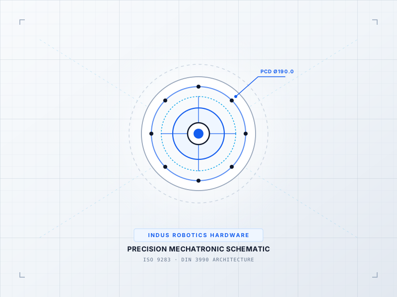
INTERACTIVE 3D CAD KINEMATICSIND-DRV-ASD48 // STEP AP242 / GLTF
IND-DRV-ASD48
Full 3D Kinematic Envelope
DATUM ORIGIN (0,0,0)
Click & drag to rotate 3D assembly · Scroll to zoom
Calibrated Geometric Model:IND-DRV-ASD48_ASSEMBLY.STEP
Conforms to ISO 10303-242 / DIN 3990. Includes full mating constraints and collision envelopes.
DatasheetPDF · 4.8 MB

ASD-48 Dual-Axis Low-Latency Digital AC Servo Drive Engineering Datasheet & Sizing Curves

DS-IND-IND-DRV-AS-2026

Audited Lab Specification

CAD 3D STEPSTEP / AP214 · 32.6 MB

ASD-48 Dual-Axis Low-Latency Digital AC Servo Drive 3D STEP Assembly Geometry Model

CAD-IND-IND-DRV-AS-STEP

Accurate C.G. Matrix

ManualPDF · 6.4 MB

ASD-48 Dual-Axis Low-Latency Digital AC Servo Drive Integration & Commissioning Manual

MAN-IND-IND-DRV-AS-2026

Official Documentation

11. Frequently Asked Questions

Technical FAQs & Integration Guidelines

Direct answers to common engineering questions regarding sizing verification, mechanical tolerances, fieldbus integration, and documentation for ASD-48 Dual-Axis Low-Latency Digital AC Servo Drive.

Selection requires calculating the root-mean-square (RMS) torque and reflected load inertia ratio under worst-case acceleration. Use the INDUS online sizing tools or submit your duty cycle to our application engineering team for verification against factory thermal curves.
12. Engineering Consultation & RFQ

Need Help Selecting the Right Product?

Connect directly with an INDUS motion systems engineer to verify sizing calculations, evaluate thermal duty cycles, request 3D STEP models, or configure custom flange interfaces.

Selected Product:ASD-48 Dual-Axis Low-Latency Digital AC Servo Drive
Product Identifier:ind-drv-asd48
Engineering Family:Servo Drives and Motor Drives
Standard Conformance:ISO 9283
Need immediate sizing advice?

• Official NDA protected technical evaluation

• 24 business hours standard proposal response

• Factory direct engineering support & CAD integration

Request Official Quotation & Application Verification

Prefilled with ASD-48 Dual-Axis Low-Latency Digital AC Servo Drive specifications. Fill in your details below.