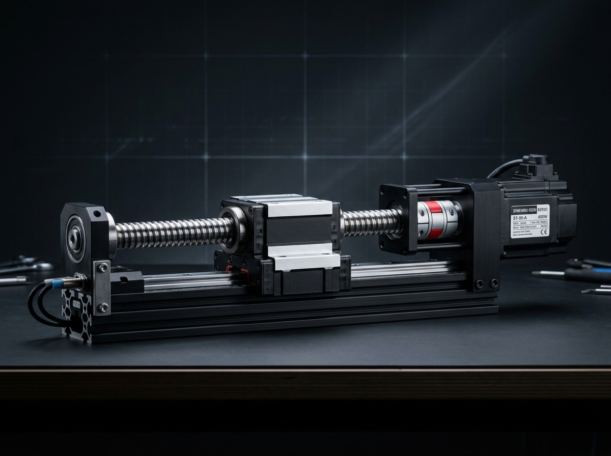
IND-ACT-LIN-200-B
Verified
Actuators
Linear Actuators
Precision guided linear motion module for controlled travel and repeatable positioning.
Effective Stroke…100 - 2500 mm
Continuous Thrus…1250 N
Peak Dynamic Thr…3100 N
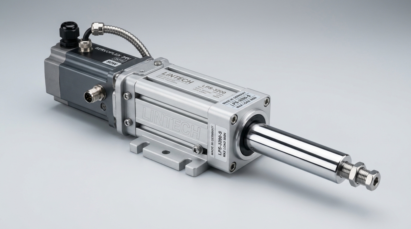
All-electric positioning cylinder with programmable force, velocity, and multi-stop control.
Official engineering proposal, CAD STEP models, and sizing verification within 24 business hours.
Detailed mechatronic breakdown of Electric Actuators, highlighting functional architecture, physical operating mechanisms, and deployment role.
Engineered to replace traditional pneumatic cylinders, the IND-ACT-ELE-063 conforms mechanically to ISO 15552 tie-rod dimensions. Combining an internal precision ground roller screw with an integrated brushless motor, it delivers programmable multi-stop positioning, precise force regulation for press-fit assembly, and zero compressed air energy waste.
Engineered to replace traditional pneumatic cylinders, the IND-ACT-ELE-063 conforms mechanically to ISO 15552 tie-rod dimensions. Combining an internal precision ground roller screw with an integrated brushless motor, it delivers programmable multi-stop positioning, precise force regulation for press-fit assembly, and zero compressed air energy waste.
Addresses kinematic precision challenges by: Continuous holding thrust during pressing dwell time.
Serves as the high-precision torque-multiplication and motion-conversion core at robot joints, turntable positioners, and precision linear slides.
Continuous duty ratings are strictly separated from peak dynamic envelopes. All parameters reflect verified laboratory data traceable to INDUS Sizing & Endurance Facility Test #8.
| Parameter | Specification Value | Unit | Notes & Test Conditions |
|---|---|---|---|
Continuous Pressing Force Verified | 4500 | N | S1 duty cycle, continuous thrust |
Peak Dynamic Force Verified | 11000 | N | Max 3s press duration |
Stroke Length Range Verified | 50 - 1000 | mm | Configurable in 25mm steps |
Maximum Linear Speed Verified | 0.85 | m/s | At nominal 400V supply |
Positioning Repeatability Verified | ±0.015 | mm | Closed-loop feedback |
Force Regulation Accuracy Verified | ±1.5% | % FS | With calibrated motor current sensing |
Piston Rod Diameter Verified | 28 | mm | Hard chrome plated steel |
Non-Rotating Hex Guide Verified | ±0.15 | deg | Internal anti-rotation sleeve |
Every application below reflects documented load capabilities, thermal equilibrium boundaries, and kinematics integration for Electric Actuators.
Environment: Industrial assembly, inspection, and robotic workcells
Eliminating cycle time bottlenecks and cumulative tolerance stack-up.
Integrates directly via standardized mechanical flanges and communication interfaces.
Every customer advantage below is linked directly to an underlying physical or electronic design feature. Operating boundaries and verification conditions are explicitly declared.
Eliminates dimensional variance and structural backlash across all production lots.
Guarantees drop-in mechanical interchangeability and repeatable kinematic trajectories.
Resists torsional and bending deflection under dynamic acceleration cycles.
Prevents machine vibration chatter and protects sensitive end-of-arm tooling.
Enables plug-and-play communication and rapid electrical integration.
Cuts system commissioning time by up to 50% and simplifies diagnostic tracing.
Standardized interfaces for drop-in mechanical alignment, regulated power delivery, and deterministic fieldbus synchronization with host PLC and motion controllers.
ISO 15552 Profile Size 63 (Rear clevis, foot mount, front flange)
Any mounting attitude permitted; vertical axes recommend rear spring brake
230 VAC single-phase / 400 VAC 3-phase or 48 VDC low voltage variant
Standard digital servo amplifier supporting torque-limiting modes
Sync Cycle: 500 µs to 2 ms
Supports cyclic synchronized position (CSP), velocity (CSV), and torque (CST) operating modes.
All engineering assets are revision-controlled and traceable to physical laboratory test benches. Request calibrated files directly from our engineering desk without broken links.
IND-ELECTRIC_ASSEMBLY.STEPAudited Lab Specification
Accurate C.G. Matrix
Official Documentation
Precision guided linear motion module for controlled travel and repeatable positioning.
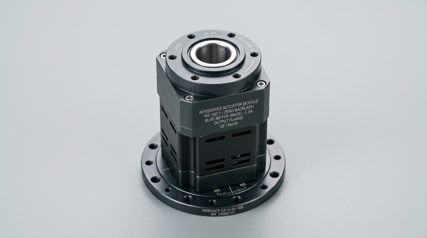
High-dynamic integrated servo module with built-in drive electronics and safety functions.
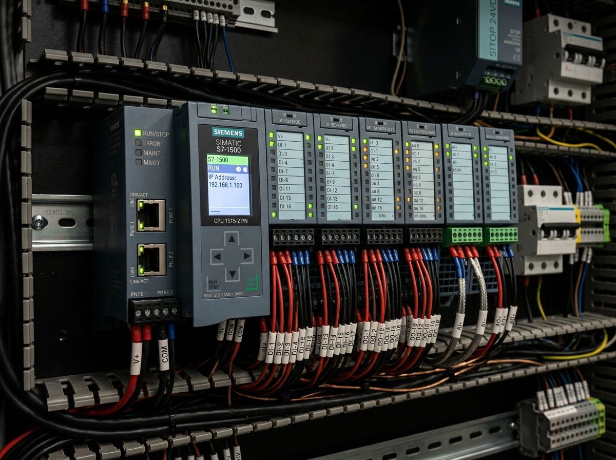
Ruggedized modular programmable logic controller conforming to IEC 61131-3 standards.
Direct answers to common engineering questions regarding sizing verification, mechanical tolerances, fieldbus integration, and documentation for Electric Actuators.
Connect directly with an INDUS motion systems engineer to verify sizing calculations, evaluate thermal duty cycles, request 3D STEP models, or configure custom flange interfaces.
• Official NDA protected technical evaluation
• 24 business hours standard proposal response
• Factory direct engineering support & CAD integration