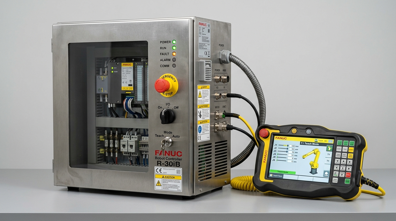
IND-CTL-RBC-X86-RT
Verified
Control Systems
Robot Controllers
Industrial-grade controller computing forward/inverse kinematics with integrated functional safety.
Coordinated Axis…Up to 16 Axes axes
Trajectory Inter…1.0 ms
EtherCAT Master …< 1.0 µs
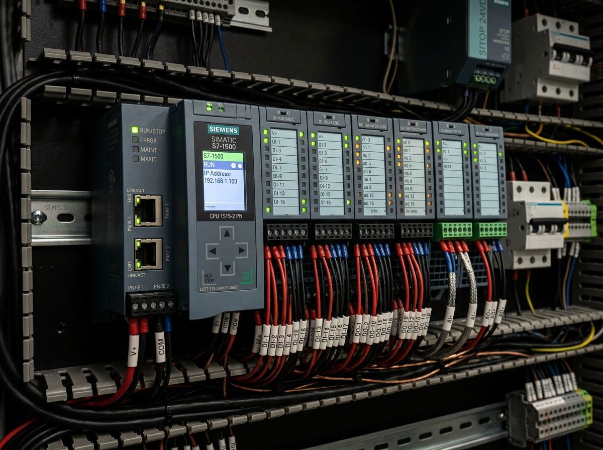
Ruggedized modular programmable logic controller conforming to IEC 61131-3 standards.
Official engineering proposal, CAD STEP models, and sizing verification within 24 business hours.
Detailed mechatronic breakdown of PLC & Automation, highlighting functional architecture, physical operating mechanisms, and deployment role.
The IND-CTL-PLC-61131 is a modular, high-reliability programmable logic controller engineered for cell-level sequencing, safety interlock management, and plant-wide industrial communication. Compliant with IEC 61131-3 programming standards, it coordinates digital and analog slice I/O, safety light curtains, pneumatic valves, and fieldbus bridges to plant SCADA/MES architectures.
The IND-CTL-PLC-61131 is a modular, high-reliability programmable logic controller engineered for cell-level sequencing, safety interlock management, and plant-wide industrial communication. Compliant with IEC 61131-3 programming standards, it coordinates digital and analog slice I/O, safety light curtains, pneumatic valves, and fieldbus bridges to plant SCADA/MES architectures.
Addresses kinematic precision challenges by: Digital and analog I/O point count for actuators, pneumatic valves, sensors, and lamps.
Acts as the central deterministic computing core or power amplifier, executing multi-axis motion trajectories and real-time fieldbus synchronization.
Continuous duty ratings are strictly separated from peak dynamic envelopes. All parameters reflect verified laboratory data traceable to INDUS Industrial Automation Test Bed #2.
| Parameter | Specification Value | Unit | Notes & Test Conditions |
|---|---|---|---|
Program Cycle Time Verified | 1.0 | ms | For 10,000 instructions |
Local Slice I/O Capacity Verified | Up to 64 Expansion Slices | modules | Direct backplane bus connection |
Maximum Digital I/O Points Verified | 1024 Points | channels | Across local and distributed fieldbus nodes |
Supported Fieldbuses Verified | PROFINET IRT, EtherNet/IP, EtherCAT, Modbus TCP | protocols | Multi-protocol dual RJ45 switch ports |
Safety PLC Option Verified | SIL 3 / Cat 4 PLe | IEC 61508 | Failsafe CPU variant with PROFIsafe / FSoE |
Operating Supply Voltage Verified | 24 VDC (19.2 - 28.8 VDC) | voltage | Industrial DC supply |
Memory Capacity Verified | 32 MB Program / 64 MB Data | memory | Flash retentive storage without battery |
Operating Temperature Range Verified | -20°C to +60°C | temp | Standard DIN rail mounting |
Every application below reflects documented load capabilities, thermal equilibrium boundaries, and kinematics integration for PLC & Automation.
Environment: Industrial assembly, inspection, and robotic workcells
Eliminating cycle time bottlenecks and cumulative tolerance stack-up.
Integrates directly via standardized mechanical flanges and communication interfaces.
Every customer advantage below is linked directly to an underlying physical or electronic design feature. Operating boundaries and verification conditions are explicitly declared.
Eliminates dimensional variance and structural backlash across all production lots.
Guarantees drop-in mechanical interchangeability and repeatable kinematic trajectories.
Resists torsional and bending deflection under dynamic acceleration cycles.
Prevents machine vibration chatter and protects sensitive end-of-arm tooling.
Enables plug-and-play communication and rapid electrical integration.
Cuts system commissioning time by up to 50% and simplifies diagnostic tracing.
Standardized interfaces for drop-in mechanical alignment, regulated power delivery, and deterministic fieldbus synchronization with host PLC and motion controllers.
Standard 35mm DIN Rail (EN 60715)
Horizontal DIN rail mounting standard; vertical mounting derates ambient temp by 5°C
24 VDC nominal (19.2 to 28.8 VDC range)
N/A
Sync Cycle: 1 ms to 10 ms user-configurable task periods
Supports cyclic synchronized position (CSP), velocity (CSV), and torque (CST) operating modes.
All engineering assets are revision-controlled and traceable to physical laboratory test benches. Request calibrated files directly from our engineering desk without broken links.
IND-PLC-AUTOMATION_ASSEMBLY.STEPAudited Lab Specification
Accurate C.G. Matrix
Official Documentation
Industrial-grade controller computing forward/inverse kinematics with integrated functional safety.
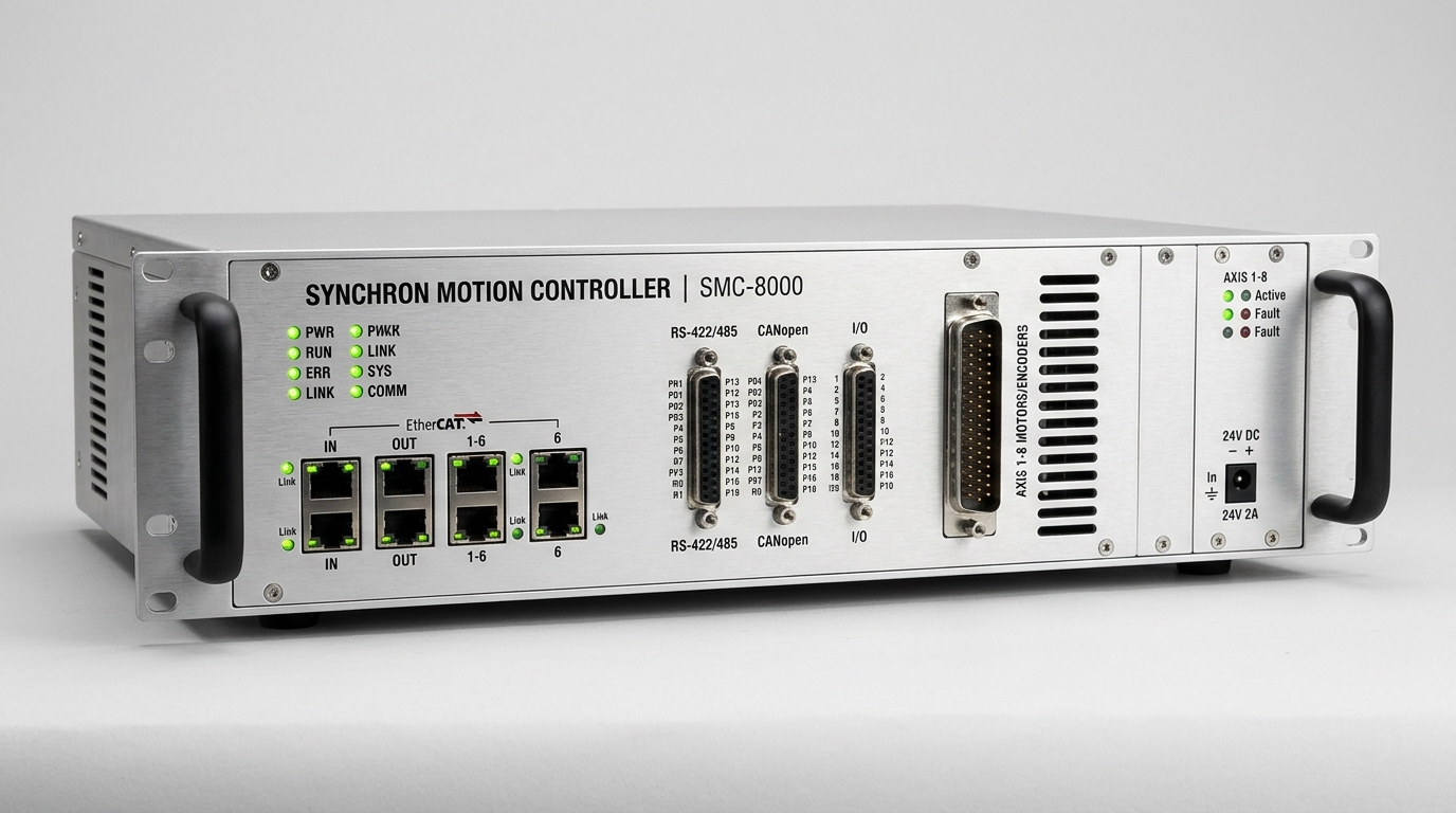
Centralized motion control engine synchronizing up to 64 coordinated axes over EtherCAT.
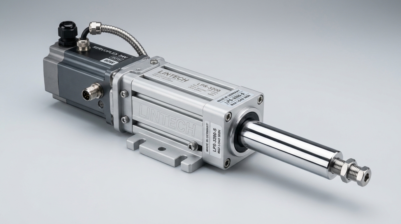
All-electric positioning cylinder with programmable force, velocity, and multi-stop control.
Direct answers to common engineering questions regarding sizing verification, mechanical tolerances, fieldbus integration, and documentation for PLC & Automation.
Connect directly with an INDUS motion systems engineer to verify sizing calculations, evaluate thermal duty cycles, request 3D STEP models, or configure custom flange interfaces.
• Official NDA protected technical evaluation
• 24 business hours standard proposal response
• Factory direct engineering support & CAD integration