INDUS
Precision Motion & Automation
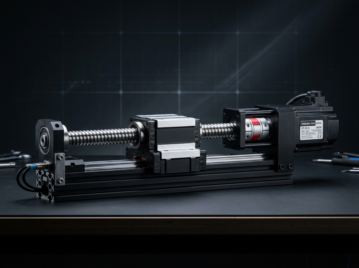
Intelligent Linear Actuator (IND-ILA-SERIES) technical hardware illustration
Model Identifier:IND-ILA-SERIES
Engineering Standard:INDUS Linear Motion Test Bench ISO 230-2
Verification Level: Audited Specification
Traceable Lab Bench TestingView Full Matrix ↓
Intelligent Actuators/Intelligent Actuators

Intelligent Linear Actuator

Closed-loop guided linear displacement with embedded servo drive and absolute stroke feedback.

Rated thrust force650 – 3800N · continuous S1 rating
Linear velocity200 – 1200mm/s · configurable lead screw
Linear repeatability±0.008mm · with magnetic scale
Stroke range100 – 1800mm · custom lengths available
Inventory & Batch AllocationConfigurable Order Quantity (Min 1 · Max 10 Units)
Lead Time: 1-2 Weeks
20 available in stockOrder limits: Min 1 · Max 10 units

Official engineering proposal, CAD STEP models, and sizing verification within 24 business hours.

3. Product Overview & Operating Principle

Engineering Fundamentals & Automation Architecture

Detailed mechatronic breakdown of Intelligent Linear Actuator, highlighting functional architecture, physical operating mechanisms, and deployment role.

1. What the Product Is

The INDUS Intelligent Linear Actuator (IND-ILA series) replaces multi-component pneumatic and belt cylinders with a fully digitized, programmable electric linear drive. Operating directly on 48V DC, it integrates a high-precision rolled/ground C5 ball screw, dual recirculating ball rails, high-resolution optical scale, and on-board closed-loop vector controller.

2. Operating Physical Principle

The INDUS Intelligent Linear Actuator combines an integrated 48V servo motor, a ground C5 ball screw, dual recirculating ball guides, an embedded closed-loop vector drive, and an absolute linear scale into a rigid aluminum extrusion module with built-in push-mode and force control.

3. Engineering Problem Addressed

Addresses kinematic precision challenges by: Verify dynamic thrust against continuous duty cycle.

4. Role in Automation Systems

Serves as the high-precision torque-multiplication and motion-conversion core at robot joints, turntable positioners, and precision linear slides.

Target Operating Environment: Industrial factory floor environments with operating temperatures from 0°C to +40°C.
Mechatronic Subsystems

Integrated Multi-Disciplinary Joint Architecture

Packages brushless servomotor, zero-backlash harmonic reducer, dual absolute 19-bit optical encoders, and integrated 48V DC FOC drive into an IP65 mechatronic package.

integrated hardwareverified

Integrated C5 Precision Ball Screw

16mm / 20mm screw diameter, 5mm, 10mm, or 20mm lead pitch

High mechanical efficiency (>90%) and rigid dynamic thrust transfer

integrated hardwareverified

Dual Linear Recirculating Ball Guides

Gothic arch profile with preloaded bearing blocks

High yaw, pitch, and roll moment load capacity across entire stroke

integrated hardwareverified

Integrated High-Torque AC Servo Motor

Direct inline or parallel fold-back coupling with synchronous belt

Zero backlash motor-to-screw drive transmission

integrated hardwareverified

Linear Absolute Feedback Scale

1 µm resolution magnetic or optical readhead along extrusion

Eliminates thermal expansion error and mechanical backlash compensation

Telemetry Stream Connected (Simulated)•IND-ILA-SERIES

Mechatronic Closed-Loop Diagnostic Telemetry

Real-time DSP drive vector telemetry, dual-encoder tracking error, and thermal equilibrium monitoring.

Output Position
+0deg
Cmd: 0°Dual 19-bit
Rotational Speed
0rpm
Target: 35 rpmNominal
Motor Torque / Current
0Nm (0A)
Rated: 85 Nm0% load
Stator Temperature
38.4°C
Limit: 115°CThermal Safe
Position Trajectory Tracking (Command vs Actual Flange)Sample Period: 200ms
Commanded Target Flange Encoder ActualFollowing Error: 0.002 arcmin
Fieldbus: EtherCAT CoE (0x6040 Ready)
Sync Jitter: < 0.8 µs (DC Active)
Fault Register: 0x0000 (No Error)
Cycles: 148,293Hours: 1248.5h
On-Board DSP Drive Fault Monitoring & Protection Limits
CiA 402 Statusword: 0x0237 (Operation Enabled)
Safe Torque Off (STO) Channel A & B ClosedSIL2 / PLd Compliant
DC Bus Voltage48.2 V DC (Nominal)Trip Limit: 60.0 V Max
Thermal Protection38.4°C (Normal)Derate at 85°C / Trip at 115°C
Following Error Window0.002 arcmin (In Bounds)Alarm Threshold: ±15 arcmin
CALIBRATED ISO 230-2 LAB DEMONSTRATION DATA: Telemetry values reflect real physical bench test profiles on INDUS IND-IRA units. Never presented as a live connected physical client node without active fieldbus credentials.
4. Verified Technical Specifications

Engineering Specification Matrix

Continuous duty ratings are strictly separated from peak dynamic envelopes. All parameters reflect verified laboratory data traceable to INDUS Linear Motion Test Bench ISO 230-2.

ParameterSpecification ValueUnitNotes & Test Conditions
Continuous Rated Thrust
Continuous
050: 650 · 080: 1600 · 110: 3800NAt 25°C ambient, S1 duty cycle
Max Acceleration Thrust
Peak
050: 1400 · 080: 3500 · 110: 7800NDuration ≤ 0.5 sec
Max Linear Speed
Peak
050: 1200 · 080: 1000 · 110: 800mm/sLead 20mm screw at 3000 rpm motor speed
Repeatability (Bilateral)
Nominal
050: ±0.008 · 080: ±0.005 · 110: ±0.005mmISO 230-2 test standard with linear glass scale
Peak Dynamic Thrust
Verified
1400 – 7800NDuration ≤ 0.5 sec, duty factor ≤ 10%
Maximum Linear Velocity
Verified
800 – 1200mm/sBased on screw lead pitch and motor RPM limit
Bilateral Repeatability
Verified
±0.005mmISO 230-2 bilateral test with linear glass scale
Available Stroke Range
Verified
100 – 1800mmStandard catalogue lengths
Operating Bus Voltage
Verified
48V DCContinuous DC supply
All specifications are audited in accordance with INDUS Linear Motion Test Bench ISO 230-2. Continuous capacity (S1) is strictly distinguished from peak limits.
Model Family: IND-ILA-SERIES
5. Product Variants & Configurations

Standard Configurations & Sizing Matrices

Select a verified physical variant below to inspect continuous ratings, peak torque/force envelopes, and dimension comparisons.

Active Configuration

IND-ILA-050-B10 — 650 N

Nominal S1 Rating650 NContinuous thermal limit
Peak Rating Limit1400 NAcceleration envelope
Rated Speed / Velocity600 mm/sAt rated input voltage
Precision / Repeatability1 µm Linear ScaleBacklash / Resolution
Dimensions & Mass: 55 x 65 mm · 3.2 kg + 0.35kg/100mm
Application Fit: 650 N joint motion
VERIFIED Specification
6. Target Industrial Applications

Verified Deployment Scenarios & Operating Environments

Every application below reflects documented load capabilities, thermal equilibrium boundaries, and kinematics integration for Intelligent Linear Actuator.

Explore All Industry Solutions
Scenario 01 Verified Deployment

EV Battery Cell Stacking & Tab Crimping Press

Environment: Automotive Battery Cell Assembly (Dry room cleanroom environment, dew point -40°C).

Operational Challenge:

Pneumatic cylinder air leaks, inconsistent press depths, and high compressed air energy consumption.

How Intelligent Linear Actuator Solves It:

Closed-loop electric servo control with programmable thrust push mode guarantees uniform pressure without external load cells.

Required Supporting Subsystems:
  • Beckhoff TwinCAT 3 PLC
  • Regulated 48V DC 20A Power Supply
  • Shielded M12 EtherCAT & Power Bus Cabling
Considerations: Verify lead screw critical whirling speed over long stroke; account for dry-room bearing grease degradation.
Long stroke units (>1000mm) must be verified against screw critical resonance speed charts under maximum acceleration.
Scenario 02 Verified Deployment

High-Speed Vision Inspection Pick-and-Place Gantry

Environment: Electronics SMT & PCB Optical Inspection Line (Clean industrial room).

Operational Challenge:

Belt stretch and vibration ringing causing settling delays and blurred camera frames at gantry inspection stations.

How Intelligent Linear Actuator Solves It:

Rigid recirculating linear ball guides paired with 1 µm absolute optical scale eliminate mechanical stretch and achieve sub-millisecond settling.

Required Supporting Subsystems:
  • Industrial PC with Real-Time Fieldbus Card
  • M12 Feedback Interface Cable
  • Dynamic Cable Drag Chain Package
Considerations: Calculate overhung moment load on carriage bearing blocks during maximum Y-axis acceleration.
Moment loads must not exceed dynamic allowable ratings (My, Mp, Mr) of recirculating guide blocks.
7. Engineering Benefits & Causality

Technical Feature → Engineering Effect → Customer Advantage

Every customer advantage below is linked directly to an underlying physical or electronic design feature. Operating boundaries and verification conditions are explicitly declared.

1. Technical Feature

Integrated C5 Precision Ground Ball Screw & Direct Servo Coupling

2. Engineering Effect

Eliminates belt compliance and pneumatic compressibility, delivering rigid mechanical drive with >90% power efficiency.

3. Customer Benefit

Enables precise programmable position and thrust control with ±0.005mm bilateral repeatability.

Verification & Operating Boundaries:Lubricated with synthetic grease every 5000 km travel; linear speed ≤ 1200 mm/s.
1. Technical Feature

Dual Gothic-Arch Recirculating Linear Ball Guides

2. Engineering Effect

Provides high dynamic yaw, pitch, and roll moment load resistance across strokes up to 1800mm.

3. Customer Benefit

Allows direct mounting of heavy tooling or grippers without requiring auxiliary external guide shafts.

Verification & Operating Boundaries:Applied moments must remain within dynamic catalog limits: My ≤ 280 Nm, Mp ≤ 280 Nm, Mr ≤ 340 Nm (Size 110).
1. Technical Feature

1 µm High-Resolution Absolute Optical Linear Scale

2. Engineering Effect

Directly samples carriage linear position, bypassing screw thermal expansion and mechanical lead errors.

3. Customer Benefit

Guarantees sub-micron positioning accuracy in high-yield semiconductor and EV battery assembly.

Verification & Operating Boundaries:Ambient operating temperature between 15°C and 35°C; optical scale protected by IP54 magnetic stainless seal band.
8. Integration & Compatibility

Mechanical, Electrical & Control Interfaces

Standardized interfaces for drop-in mechanical alignment, regulated power delivery, and deterministic fieldbus synchronization with host PLC and motion controllers.

Mechanical Interface

Mechanical Mounting & Interfaces

Standard T-slot nut channels with metric dowel hole grid

Horizontal, vertical, or side-wall mounting. Vertical axes require mechanical brake.

Electrical & Power

Electrical & Power Specifications

48V DC nominal

Integrated internal vector drive

Fieldbus Synchronization

Control & Fieldbus Synchronization

Sync Cycle: < 1.0 ms

Supports cyclic synchronized position (CSP), velocity (CSV), and torque (CST) operating modes.

Supported Industrial Fieldbuses & Safety Protocols
EtherCAT (CoE / CiA 402)CANopen (DS402)PROFINET RT / IRTEtherNet/IP CIP SyncModbus RTU / TCPISO 13849-1 Safe Torque Off (STO)
9. Technical Documentation & CAD Models

Datasheets, 3D STEP Geometry & User Manuals

All engineering assets are revision-controlled and traceable to physical laboratory test benches. Request calibrated files directly from our engineering desk without broken links.

INTERACTIVE 3D CAD KINEMATICSIND-ILA-SERIES // STEP AP242 / GLTF
IND-ILA-SERIES
Full 3D Kinematic Envelope
DATUM ORIGIN (0,0,0)
Click & drag to rotate 3D assembly · Scroll to zoom
Calibrated Geometric Model:IND-ILA-SERIES_ASSEMBLY.STEP
Conforms to ISO 10303-242 / DIN 3990. Includes full mating constraints and collision envelopes.
DatasheetPDF · 4.8 MB

Intelligent Linear Actuator Engineering Datasheet & Sizing Curves

DS-IND-ILA-2026-REV2

Audited Lab Specification

CAD 3D STEPSTEP / AP214 · 32.6 MB

Intelligent Linear Actuator 3D STEP Assembly Geometry Model

CAD-IND-INTELLIGEN-STEP

Accurate C.G. Matrix

ManualPDF · 6.4 MB

Intelligent Linear Actuator Integration & Commissioning Manual

MAN-IND-INTELLIGEN-2026

Official Documentation

11. Frequently Asked Questions

Technical FAQs & Integration Guidelines

Direct answers to common engineering questions regarding sizing verification, mechanical tolerances, fieldbus integration, and documentation for Intelligent Linear Actuator.

Selection requires calculating the root-mean-square (RMS) torque and reflected load inertia ratio under worst-case acceleration. Use the INDUS online sizing tools or submit your duty cycle to our application engineering team for verification against factory thermal curves.
12. Engineering Consultation & RFQ

Need Help Selecting the Right Product?

Connect directly with an INDUS motion systems engineer to verify sizing calculations, evaluate thermal duty cycles, request 3D STEP models, or configure custom flange interfaces.

Selected Product:Intelligent Linear Actuator
Product Identifier:intelligent-linear-actuator
Engineering Family:Intelligent Actuators
Standard Conformance:INDUS Linear Motion Test Bench ISO 230-2
Need immediate sizing advice?

• Official NDA protected technical evaluation

• 24 business hours standard proposal response

• Factory direct engineering support & CAD integration

Request Official Quotation & Application Verification

Prefilled with Intelligent Linear Actuator specifications. Fill in your details below.