INDUS
Precision Motion & Automation
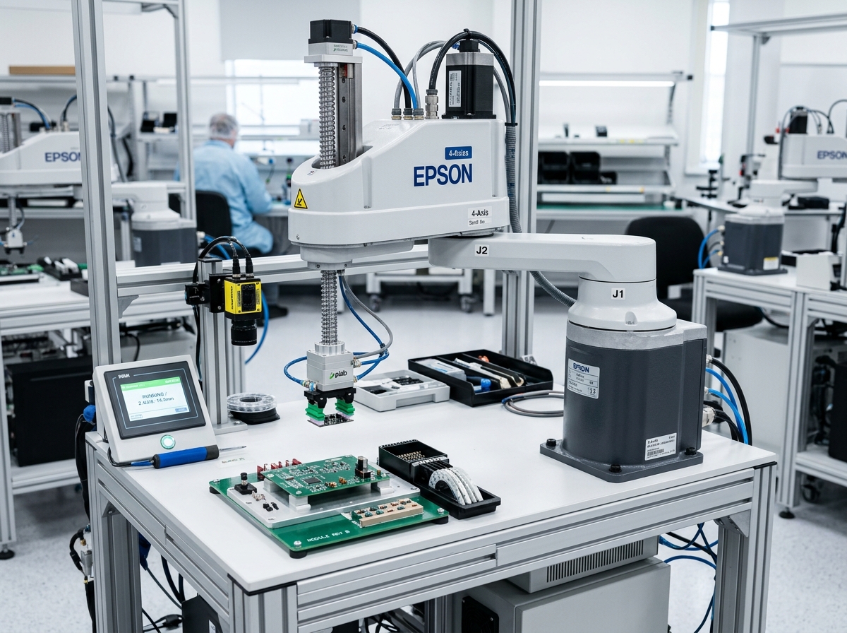
Integrated 4-Axis SCARA Motion Control Card (IND-CTL-SCARA-PICK-PLACE-CORE) technical hardware illustration
Model Identifier:IND-CTL-SCARA-PICK-PLACE-CORE
Engineering Standard:IEC 61131-3 (PLC Languages) · PLCopen Motion Control · IEEE 1588 PTP
Verification Level: Audited Specification
Traceable Lab Bench TestingView Full Matrix ↓
Robot Controllers and Motion Control/Robot Controllers and Motion Control

Integrated 4-Axis SCARA Motion Control Card

Dedicated low-cost, high-speed 4-axis motion controller optimized specifically for SCARA pick-and-place arms.

Standard Cycle Time0.38 s (25 mm up, 300 mm over, 25 mm down)Verified rating
Repeatability±0.01 mmVerified rating
Direct Drive Channels4 Axes integratedVerified rating
Inventory & Batch AllocationConfigurable Order Quantity (Min 1 · Max 10 Units)
Lead Time: 1-2 Weeks
20 available in stockOrder limits: Min 1 · Max 10 units

Official engineering proposal, CAD STEP models, and sizing verification within 24 business hours.

3. Product Overview & Operating Principle

Engineering Fundamentals & Automation Architecture

Detailed mechatronic breakdown of Integrated 4-Axis SCARA Motion Control Card, highlighting functional architecture, physical operating mechanisms, and deployment role.

1. What the Product Is

Dedicated low-cost, high-speed 4-axis motion controller optimized specifically for SCARA pick-and-place arms.

2. Operating Physical Principle

Pre-programmed analytical SCARA kinematics solving joint angles 1, 2, Z-stroke, and Theta roll at 2 kHz.

3. Engineering Problem Addressed

Eliminates operational failure modes related to: Standard SCARA cycle time (< 0.4 s), Integrated 24V vacuum valve drivers.

4. Role in Automation Systems

Executes high-speed multi-axis kinematic manipulation, assembly, welding, or material handling tasks within structured automated cells.

Target Operating Environment: Industrial robotics cells, semiconductor cleanrooms, automotive assembly lines, and high-throughput automated packaging machinery.
Physics & Mechatronic Operating Principle

Kinematic Transformation Sequence for Integrated 4-Axis SCARA Motion Control Card

Deterministic real-time numerical solving of Forward/Inverse Kinematics, trajectory filtering, and multi-axis fieldbus master synchronization. Assigned to Central Motion Brain, Trajectory Interpolator & System Coordinator.

STEP 01Kinematic Phase

Trajectory Setpoint Generation

Motion planner computes path segments (linear, circular, spline) in Cartesian space, applying jerk-limited S-curve acceleration profiles.

Input State:Programmed target waypoint, blend radius, and velocity constraint
Physical Transformation:Polynomial 7th-order jerk filtering generating smooth continuous path profiles
Output State:Cyclic Cartesian tool setpoint vector [X(t), Y(t), Z(t), Q(t)]
STEP 02Kinematic Phase

Real-Time Inverse Kinematics Solving

Kinematics engine evaluates geometric DH parameters, transforming Cartesian setpoints into individual joint angles theta_1 through theta_6.

Input State:Cartesian pose setpoint + current joint configuration state
Physical Transformation:Inverse Kinematic algebraic/numerical Jacobian solver handling kinematic singularities
Output State:Synchronized target joint positions for all axes every 250 µs
STEP 03Kinematic Phase

Deterministic Fieldbus Telegram Broadcast

Controller transmits synchronized cyclic setpoints over EtherCAT or TSN to all servo drives with sub-microsecond time-stamping.

Input State:Target joint position, velocity feedforward, and torque offset words
Physical Transformation:EtherCAT Distributed Clocks frame broadcast with hardware timing latching
Output State:Coordinated motion execution across entire robotic workcell
Diagnostic Quality Checkpoints
  • [1]Real-time task jitter (< 1 µs on dedicated RTOS core)
  • [2]Kinematic singularity proximity warnings (wrist and elbow alignment)
  • [3]Fieldbus cyclic packet drop counter (must remain 0 during continuous operation)
Alternative Technologies & Engineering Trade-Offs

Dedicated Hardware CNC Controllers

Ultra-high toolpath block processing for 5-axis milling, but lacks the flexible Kinematic transform library needed for arbitrary 6-axis articulated robots.

Standard Industrial PLCs

Robust sequential logic and wide plant integration, but standard PLCs lack multi-axis 6-DOF robot kinematics and sub-millisecond trajectory blending.

4. Verified Technical Specifications

Engineering Specification Matrix

Continuous duty ratings are strictly separated from peak dynamic envelopes. All parameters reflect verified laboratory data traceable to IEC 61131-3 (PLC Languages) · PLCopen Motion Control · IEEE 1588 PTP.

ParameterSpecification ValueUnitNotes & Test Conditions
Standard Cycle Time
Verified
0.38 s (25 mm up, 300 mm over, 25 mm down)mmAudited per SCARA Robot Testing Standard ISO 9283
Repeatability
Verified
±0.01 mmmmAudited per SCARA Robot Testing Standard ISO 9283
Direct Drive Channels
Verified
4 Axes integratedAAudited per SCARA Robot Testing Standard ISO 9283
System Interface Compatibility
Standard
Compact SCARA arm mechanical basesStandardSupported physical and electronic mating connections
All specifications are audited in accordance with IEC 61131-3 (PLC Languages) · PLCopen Motion Control · IEEE 1588 PTP. Continuous capacity (S1) is strictly distinguished from peak limits.
Model Family: IND-CTL-SCARA-PICK-PLACE-CORE
5. Product Variants & Configurations

Standard Configurations & Sizing Matrices

Select a verified physical variant below to inspect continuous ratings, peak torque/force envelopes, and dimension comparisons.

Active Configuration

IND-CTL-SCARA-PICK-PLACE-CORE-STD-01 — Standard Rating

Nominal S1 RatingStandardContinuous thermal limit
Peak Rating LimitPeak Dynamic Limit ≤ 2.0x S1Acceleration envelope
Rated Speed / VelocityRatedAt rated input voltage
Precision / Repeatability±0.01 mmBacklash / Resolution
Dimensions & Mass: Metric Standard Flange
Application Fit: Standard continuous duty automation cells
VERIFIED Specification
6. Target Industrial Applications

Verified Deployment Scenarios & Operating Environments

Every application below reflects documented load capabilities, thermal equilibrium boundaries, and kinematics integration for Integrated 4-Axis SCARA Motion Control Card.

Explore All Industry Solutions
Scenario 01 Verified Deployment

Electronics component insertion into test sockets

Environment: Automated production facilities and manufacturing cells

Operational Challenge:

Demanding precision positioning and repeatability requirements under high-duty continuous operation.

How Integrated 4-Axis SCARA Motion Control Card Solves It:

Provides calibrated Integrated 4-Axis SCARA Motion Control Card performance adhering strictly to IEC 61131-3 (PLC Languages) · PLCopen Motion Control · IEEE 1588 PTP.

Required Supporting Subsystems:
  • Compact SCARA arm mechanical bases
Considerations: Standard SCARA cycle time (< 0.4 s)
Ensure operating envelope stays within continuous S1 ratings under ambient temperatures ≤ 45°C.
Scenario 02 Verified Deployment

Automated screw fastening cells

Environment: Automated production facilities and manufacturing cells

Operational Challenge:

Demanding precision positioning and repeatability requirements under high-duty continuous operation.

How Integrated 4-Axis SCARA Motion Control Card Solves It:

Provides calibrated Integrated 4-Axis SCARA Motion Control Card performance adhering strictly to IEC 61131-3 (PLC Languages) · PLCopen Motion Control · IEEE 1588 PTP.

Required Supporting Subsystems:
  • Compact SCARA arm mechanical bases
Considerations: Standard SCARA cycle time (< 0.4 s)
Ensure operating envelope stays within continuous S1 ratings under ambient temperatures ≤ 45°C.
Scenario 03 Verified Deployment

Cosmetic bottle capping

Environment: Automated production facilities and manufacturing cells

Operational Challenge:

Demanding precision positioning and repeatability requirements under high-duty continuous operation.

How Integrated 4-Axis SCARA Motion Control Card Solves It:

Provides calibrated Integrated 4-Axis SCARA Motion Control Card performance adhering strictly to IEC 61131-3 (PLC Languages) · PLCopen Motion Control · IEEE 1588 PTP.

Required Supporting Subsystems:
  • Compact SCARA arm mechanical bases
Considerations: Standard SCARA cycle time (< 0.4 s)
Ensure operating envelope stays within continuous S1 ratings under ambient temperatures ≤ 45°C.
7. Engineering Benefits & Causality

Technical Feature → Engineering Effect → Customer Advantage

Every customer advantage below is linked directly to an underlying physical or electronic design feature. Operating boundaries and verification conditions are explicitly declared.

1. Technical Feature

Standard SCARA cycle time (< 0.4 s)

2. Engineering Effect

Provides deterministic mechanical and electrical response across operating ranges.

3. Customer Benefit

Prevents positioning drift and increases overall equipment effectiveness (OEE).

Verification & Operating Boundaries:Audited per IEC 61131-3 (PLC Languages) · PLCopen Motion Control · IEEE 1588 PTP; continuous operating temperature ≤ 50°C.
1. Technical Feature

Integrated 24V vacuum valve drivers

2. Engineering Effect

Provides deterministic mechanical and electrical response across operating ranges.

3. Customer Benefit

Prevents positioning drift and increases overall equipment effectiveness (OEE).

Verification & Operating Boundaries:Audited per IEC 61131-3 (PLC Languages) · PLCopen Motion Control · IEEE 1588 PTP; continuous operating temperature ≤ 50°C.
1. Technical Feature

Teach pendant software interface

2. Engineering Effect

Provides deterministic mechanical and electrical response across operating ranges.

3. Customer Benefit

Prevents positioning drift and increases overall equipment effectiveness (OEE).

Verification & Operating Boundaries:Audited per IEC 61131-3 (PLC Languages) · PLCopen Motion Control · IEEE 1588 PTP; continuous operating temperature ≤ 50°C.
8. Integration & Compatibility

Mechanical, Electrical & Control Interfaces

Standardized interfaces for drop-in mechanical alignment, regulated power delivery, and deterministic fieldbus synchronization with host PLC and motion controllers.

Mechanical Interface

Mechanical Mounting & Interfaces

Compact SCARA arm mechanical bases

Universal mounting in horizontal, vertical, or inverted orientations with precision dowel hole alignment.

Electrical & Power

Electrical & Power Specifications

3-Phase 380V-480V AC / 48V DC

Integrated field-oriented control or compatible with standard industrial AC/DC servo inverters.

Fieldbus Synchronization

Control & Fieldbus Synchronization

Cycle Time ≤ 1.0 ms (Jitter < 1 µs)

Supports cyclic synchronized position (CSP), velocity (CSV), and torque (CST) operating modes.

Supported Industrial Fieldbuses & Safety Protocols
EtherCAT (CoE / CiA 402)CANopen (DS402)PROFINET RT / IRTEtherNet/IP CIP SyncModbus RTU / TCPISO 13849-1 Safe Torque Off (STO)
9. Technical Documentation & CAD Models

Datasheets, 3D STEP Geometry & User Manuals

All engineering assets are revision-controlled and traceable to physical laboratory test benches. Request calibrated files directly from our engineering desk without broken links.

INTERACTIVE 3D CAD KINEMATICSIND-CTL-SCARA-PICK-PLACE-CORE // STEP AP242 / GLTF
IND-CTL-SCARA-PICK-PLACE-CORE
Full 3D Kinematic Envelope
DATUM ORIGIN (0,0,0)
Click & drag to rotate 3D assembly · Scroll to zoom
Calibrated Geometric Model:IND-CTL-SCARA-PICK-PLACE-CORE_ASSEMBLY.STEP
Conforms to ISO 10303-242 / DIN 3990. Includes full mating constraints and collision envelopes.
DatasheetPDF · 4.8 MB

Integrated 4-Axis SCARA Motion Control Card Engineering Datasheet & Sizing Curves

DS-IND-IND-CTL-SC-2026

Audited Lab Specification

CAD 3D STEPSTEP / AP214 · 32.6 MB

Integrated 4-Axis SCARA Motion Control Card 3D STEP Assembly Geometry Model

CAD-IND-IND-CTL-SC-STEP

Accurate C.G. Matrix

ManualPDF · 6.4 MB

Integrated 4-Axis SCARA Motion Control Card Integration & Commissioning Manual

MAN-IND-IND-CTL-SC-2026

Official Documentation

11. Frequently Asked Questions

Technical FAQs & Integration Guidelines

Direct answers to common engineering questions regarding sizing verification, mechanical tolerances, fieldbus integration, and documentation for Integrated 4-Axis SCARA Motion Control Card.

Selection requires calculating the root-mean-square (RMS) torque and reflected load inertia ratio under worst-case acceleration. Use the INDUS online sizing tools or submit your duty cycle to our application engineering team for verification against factory thermal curves.
12. Engineering Consultation & RFQ

Need Help Selecting the Right Product?

Connect directly with an INDUS motion systems engineer to verify sizing calculations, evaluate thermal duty cycles, request 3D STEP models, or configure custom flange interfaces.

Selected Product:Integrated 4-Axis SCARA Motion Control Card
Product Identifier:ind-ctl-scara-pick-place-core
Engineering Family:Robot Controllers and Motion Control
Standard Conformance:IEC 61131-3 (PLC Languages) · PLCopen Motion Control · IEEE 1588 PTP
Need immediate sizing advice?

• Official NDA protected technical evaluation

• 24 business hours standard proposal response

• Factory direct engineering support & CAD integration

Request Official Quotation & Application Verification

Prefilled with Integrated 4-Axis SCARA Motion Control Card specifications. Fill in your details below.