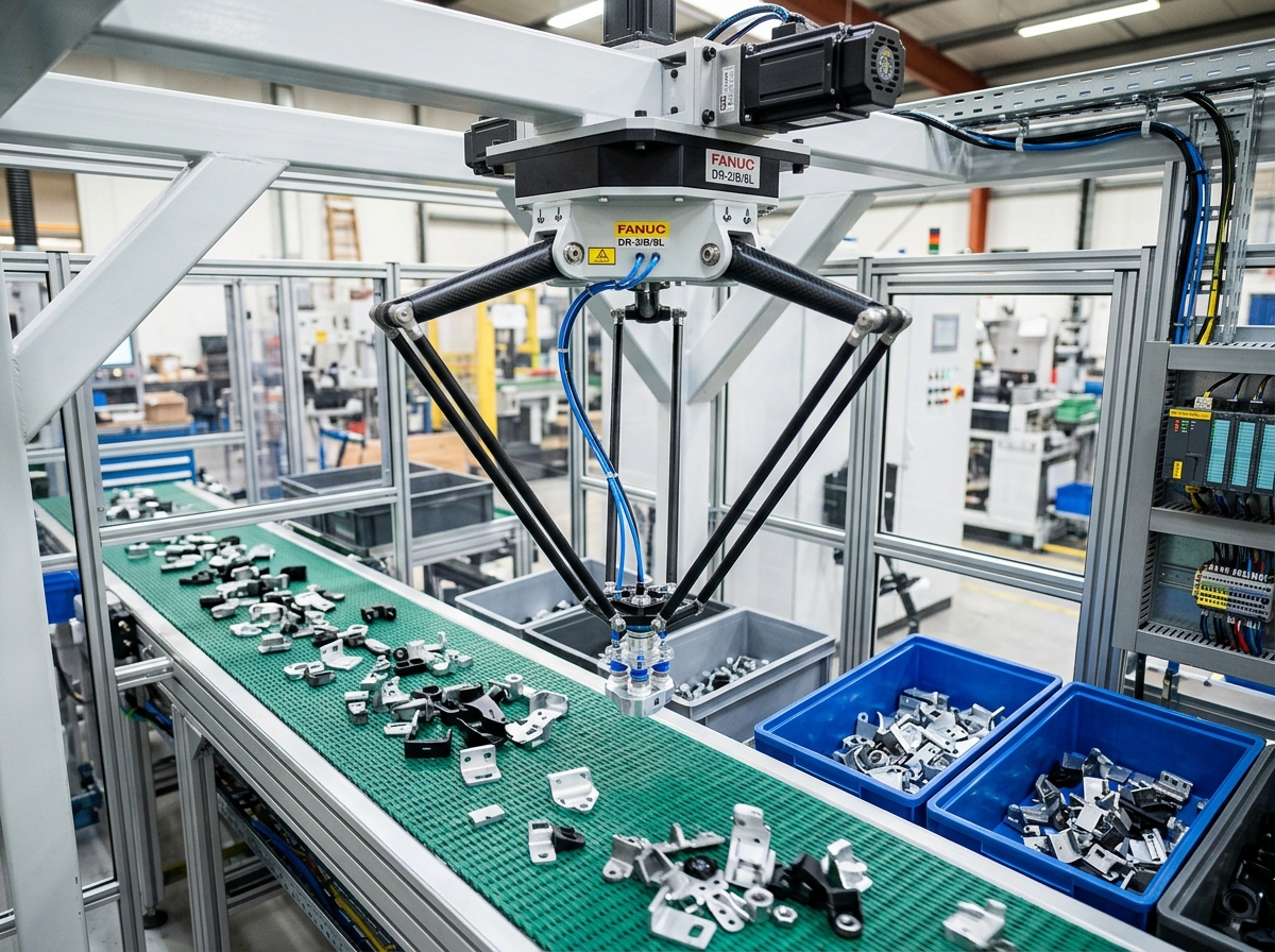
IND-ARM-DLT-1200-F
Verified
Robotic Arms
Pick & Place Robots
Ceiling-mounted delta robot achieving up to 180 picks per minute on moving conveyor lines.
Rated Payload Ca…3.0 kg
Maximum Payload …6.0 kg
Working Envelope…1200 mm
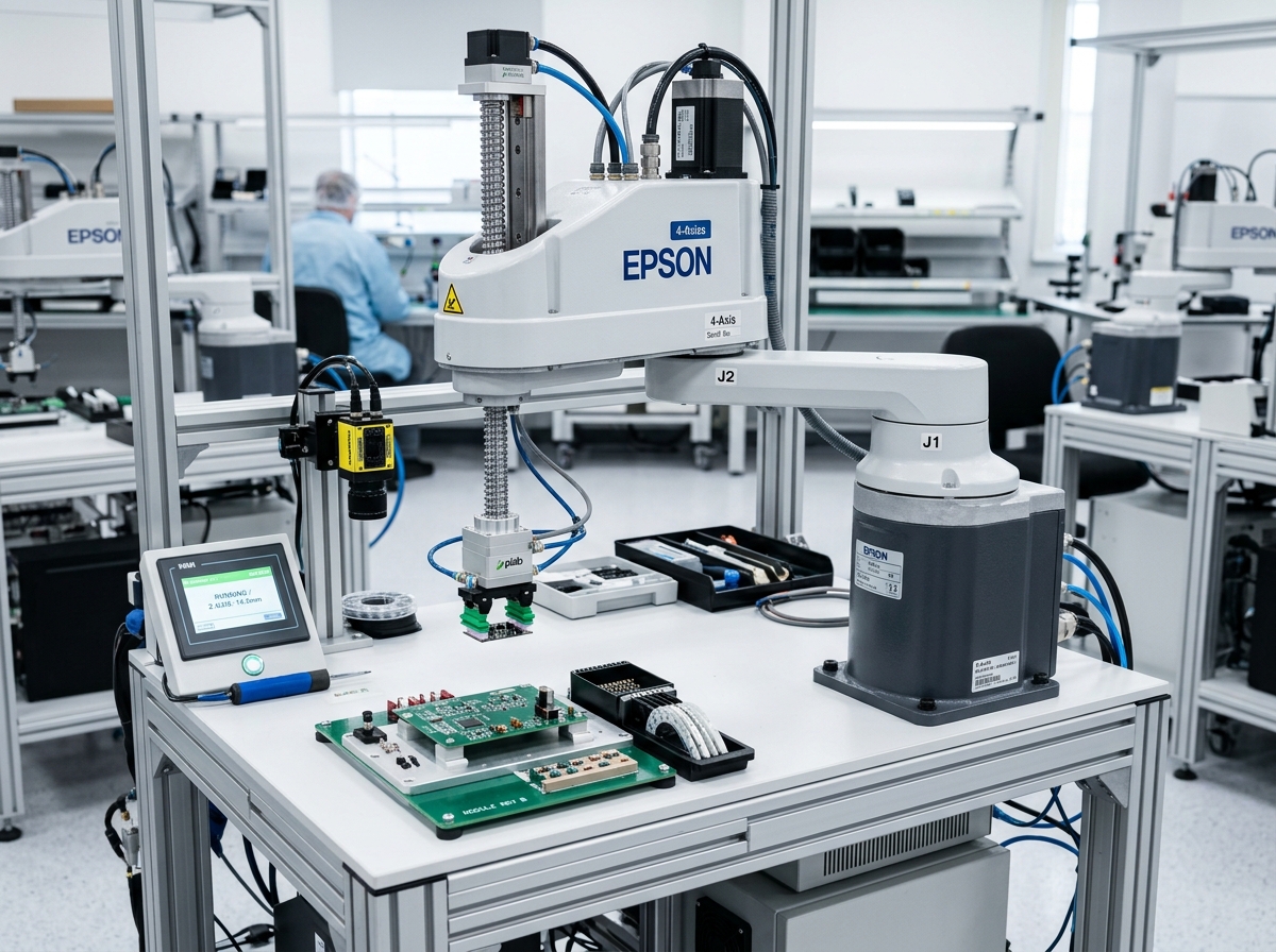
Fast SCARA and Cartesian robotic arms optimized for planar assembly and packaging cycles.
Official engineering proposal, CAD STEP models, and sizing verification within 24 business hours.
Detailed mechatronic breakdown of 4-Axis Robots, highlighting functional architecture, physical operating mechanisms, and deployment role.
The IND-ARM-SCA-600 is a high-speed 4-axis SCARA (Selective Compliance Articulated Robot Arm) engineered for high-throughput assembly, screwdriving, dispensing, and electronic component insertion. Utilizing rigid cylindrical joints in the horizontal X-Y plane and a stiff vertical ballscrew-spline quill (Z and Theta), it delivers sub-millimeter insertion precision with cycle times down to 0.38 seconds.
The IND-ARM-SCA-600 is a high-speed 4-axis SCARA (Selective Compliance Articulated Robot Arm) engineered for high-throughput assembly, screwdriving, dispensing, and electronic component insertion. Utilizing rigid cylindrical joints in the horizontal X-Y plane and a stiff vertical ballscrew-spline quill (Z and Theta), it delivers sub-millimeter insertion precision with cycle times down to 0.38 seconds.
Addresses kinematic precision challenges by: End-effector mass plus payload: verify total moment of inertia J_z around Theta axis.
Executes high-speed multi-axis kinematic manipulation, assembly, welding, or material handling tasks within structured automated cells.
Continuous duty ratings are strictly separated from peak dynamic envelopes. All parameters reflect verified laboratory data traceable to INDUS Robot Kinematics Lab ISO 9283 Test Rig #1.
| Parameter | Specification Value | Unit | Notes & Test Conditions |
|---|---|---|---|
Nominal Wrist Payload Verified | 3.0 | kg | At maximum speed cycle |
Maximum Payload Capacity Verified | 6.0 | kg | With reduced Z-axis acceleration |
Horizontal Maximum Reach Verified | 600 | mm | R_max horizontal envelope |
Z-Axis Vertical Stroke Verified | 200 | mm | Ball screw spline quill travel (300mm option) |
Standard Cycle Time Verified | 0.38 | s | 25mm up, 300mm over, 25mm down with 2kg load |
Pose Repeatability (X-Y) Verified | ±0.015 | mm | At stabilized 20°C room temperature |
Z-Axis Height Repeatability Verified | ±0.010 | mm | Direct linear ball screw drive |
Theta (J4) Angular Repeatability Verified | ±0.005 | deg | Harmonic drive hollow quill |
Maximum Composite Speed Verified | 7200 | mm/s | Combined J1 + J2 + Z sweep |
Total Manipulator Mass Verified | 28.5 | kg | Arm body without tool tooling |
Every application below reflects documented load capabilities, thermal equilibrium boundaries, and kinematics integration for 4-Axis Robots.
Environment: Industrial assembly, inspection, and robotic workcells
Eliminating cycle time bottlenecks and cumulative tolerance stack-up.
Integrates directly via standardized mechanical flanges and communication interfaces.
Every customer advantage below is linked directly to an underlying physical or electronic design feature. Operating boundaries and verification conditions are explicitly declared.
Eliminates dimensional variance and structural backlash across all production lots.
Guarantees drop-in mechanical interchangeability and repeatable kinematic trajectories.
Resists torsional and bending deflection under dynamic acceleration cycles.
Prevents machine vibration chatter and protects sensitive end-of-arm tooling.
Enables plug-and-play communication and rapid electrical integration.
Cuts system commissioning time by up to 50% and simplifies diagnostic tracing.
Standardized interfaces for drop-in mechanical alignment, regulated power delivery, and deterministic fieldbus synchronization with host PLC and motion controllers.
Rigid Base Pedestal Mount (4-Bolt Pattern)
Floor pedestal mount standard; wall mount or inverted ceiling mount available
Single-Phase 200-240 VAC, 50/60 Hz
Dedicated compact multi-axis robot controller cabinet
Sync Cycle: 1 ms trajectory interpolation
Supports cyclic synchronized position (CSP), velocity (CSV), and torque (CST) operating modes.
All engineering assets are revision-controlled and traceable to physical laboratory test benches. Request calibrated files directly from our engineering desk without broken links.
IND-4-AXIS_ASSEMBLY.STEPAudited Lab Specification
Accurate C.G. Matrix
Official Documentation
Ceiling-mounted delta robot achieving up to 180 picks per minute on moving conveyor lines.
High-accuracy robotic assembly cell combining vision, force sensing, and automatic tool changing.
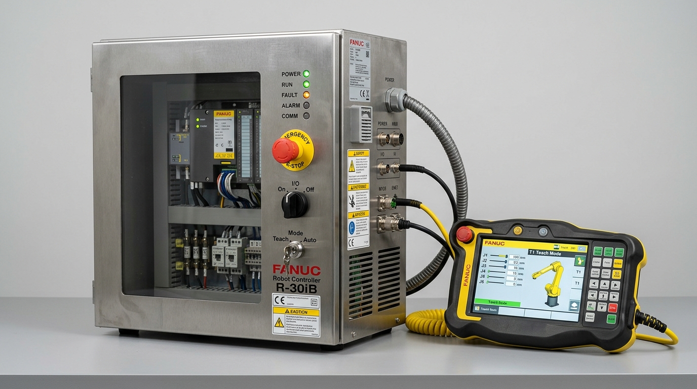
Industrial-grade controller computing forward/inverse kinematics with integrated functional safety.
Direct answers to common engineering questions regarding sizing verification, mechanical tolerances, fieldbus integration, and documentation for 4-Axis Robots.
Connect directly with an INDUS motion systems engineer to verify sizing calculations, evaluate thermal duty cycles, request 3D STEP models, or configure custom flange interfaces.
• Official NDA protected technical evaluation
• 24 business hours standard proposal response
• Factory direct engineering support & CAD integration