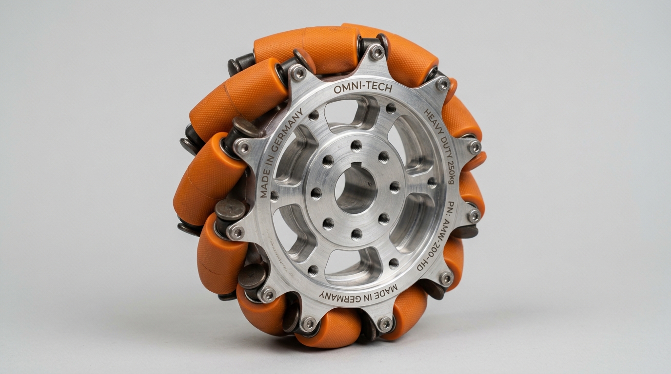
IND-WHL-OMN-150-SS
Verified
Robotic Wheels
Omni Wheels
Multi-roller wheel allowing forward traction while rolling freely in transverse directions.
Wheel Outer Diam…152 mm
Hub Width48 mm
Max Static Radia…350 kg
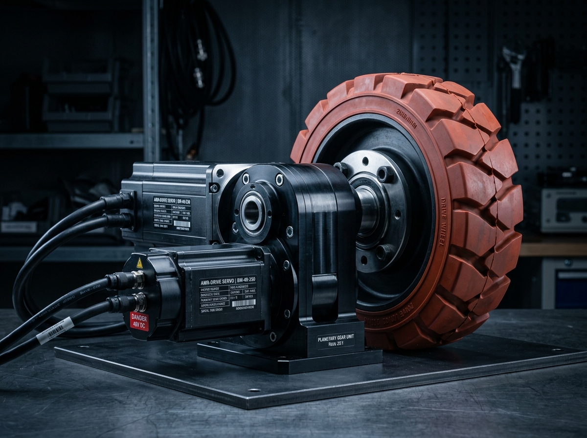
Traction wheel unit with integrated planetary gearbox and electromagnetic brake.
Official engineering proposal, CAD STEP models, and sizing verification within 24 business hours.
Detailed mechatronic breakdown of Drive Wheels, highlighting functional architecture, physical operating mechanisms, and deployment role.
The IND-WHL-DRV-200 is an integrated traction drive wheel combining a high-efficiency 48V brushless permanent magnet motor, a multi-stage high-torque planetary gearbox, an electromagnetic parking/safety brake, and a high-load 95 Shore A polyurethane tire into a single compact hub. Engineered specifically for automated guided vehicles (AGVs) and warehouse AMRs.
The IND-WHL-DRV-200 is an integrated traction drive wheel combining a high-efficiency 48V brushless permanent magnet motor, a multi-stage high-torque planetary gearbox, an electromagnetic parking/safety brake, and a high-load 95 Shore A polyurethane tire into a single compact hub. Engineered specifically for automated guided vehicles (AGVs) and warehouse AMRs.
Addresses kinematic precision challenges by: Gross Vehicle Weight (GVW) including payload and chassis mass.
Executes high-speed multi-axis kinematic manipulation, assembly, welding, or material handling tasks within structured automated cells.
Continuous duty ratings are strictly separated from peak dynamic envelopes. All parameters reflect verified laboratory data traceable to INDUS Mobile Robotics Dynamometer Rig #1.
| Parameter | Specification Value | Unit | Notes & Test Conditions |
|---|---|---|---|
Wheel Outer Diameter Verified | 200 | mm | Standard polyurethane tread |
Tread Width Verified | 75 | mm | Ground contact patch |
Max Static Radial Load Verified | 850 | kg | At zero velocity |
Rated Dynamic Payload Verified | 500 | kg | Continuous rolling at 1.5 m/s |
Continuous Traction Force Verified | 620 | N | S1 continuous at 48VDC |
Peak Acceleration Force Verified | 1450 | N | Duration ≤ 3.0s |
Rated Travel Velocity Verified | 1.8 | m/s | At 175 rpm wheel speed |
Maximum Velocity Verified | 2.4 | m/s | Concrete warehouse floor |
Holding Brake Torque Verified | 18.0 | Nm | Spring-applied 24V release brake |
Tire Tread Material Verified | Vulkollan / Polyurethane 95 Shore A | durometer | Low rolling resistance compound |
Every application below reflects documented load capabilities, thermal equilibrium boundaries, and kinematics integration for Drive Wheels.
Environment: Industrial assembly, inspection, and robotic workcells
Eliminating cycle time bottlenecks and cumulative tolerance stack-up.
Integrates directly via standardized mechanical flanges and communication interfaces.
Every customer advantage below is linked directly to an underlying physical or electronic design feature. Operating boundaries and verification conditions are explicitly declared.
Eliminates dimensional variance and structural backlash across all production lots.
Guarantees drop-in mechanical interchangeability and repeatable kinematic trajectories.
Resists torsional and bending deflection under dynamic acceleration cycles.
Prevents machine vibration chatter and protects sensitive end-of-arm tooling.
Enables plug-and-play communication and rapid electrical integration.
Cuts system commissioning time by up to 50% and simplifies diagnostic tracing.
Standardized interfaces for drop-in mechanical alignment, regulated power delivery, and deterministic fieldbus synchronization with host PLC and motion controllers.
Rigid Chassis Mounting Bracket (4-Point Flange)
Vertical suspension mount with optional spring damper kit
24 VDC to 48 VDC nominal battery bus
Dedicated dual-channel or single-channel AMR low-voltage servo drive
Sync Cycle: 1 ms to 5 ms
Supports cyclic synchronized position (CSP), velocity (CSV), and torque (CST) operating modes.
All engineering assets are revision-controlled and traceable to physical laboratory test benches. Request calibrated files directly from our engineering desk without broken links.
IND-DRIVE_ASSEMBLY.STEPAudited Lab Specification
Accurate C.G. Matrix
Official Documentation
Multi-roller wheel allowing forward traction while rolling freely in transverse directions.
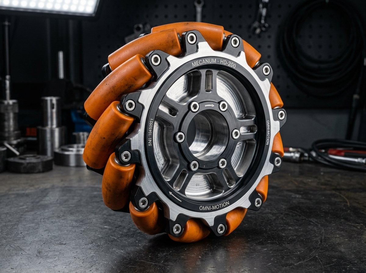
45-degree angled roller wheel enabling full holonomic movement on flat industrial floors.
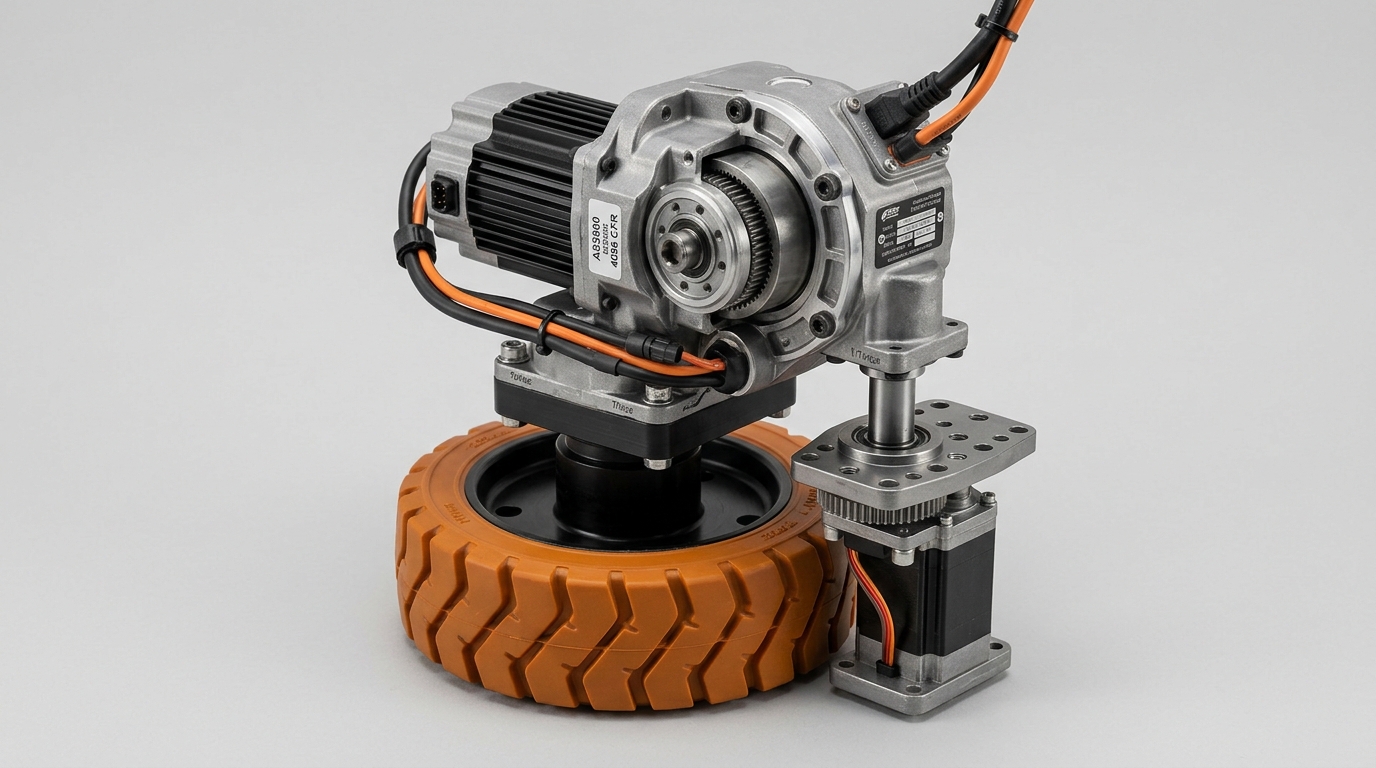
All-in-one traction, steering, reduction, and feedback unit for fast vehicle chassis integration.
Direct answers to common engineering questions regarding sizing verification, mechanical tolerances, fieldbus integration, and documentation for Drive Wheels.
Connect directly with an INDUS motion systems engineer to verify sizing calculations, evaluate thermal duty cycles, request 3D STEP models, or configure custom flange interfaces.
• Official NDA protected technical evaluation
• 24 business hours standard proposal response
• Factory direct engineering support & CAD integration