INDUS
Precision Motion & Automation
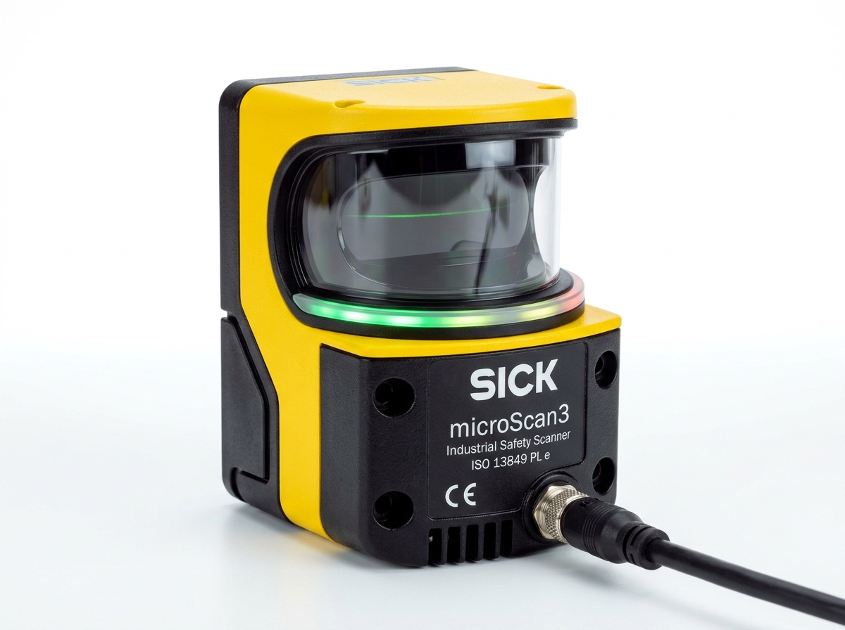
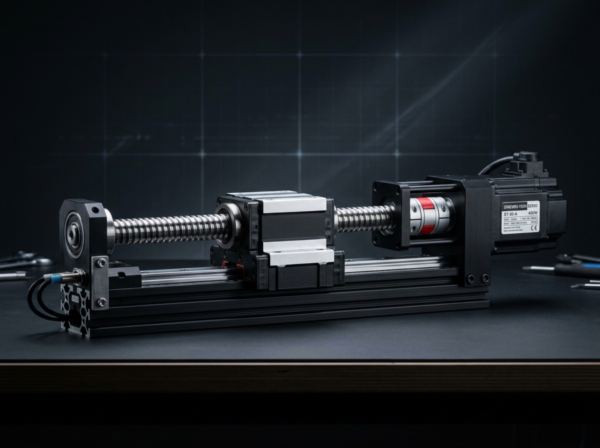
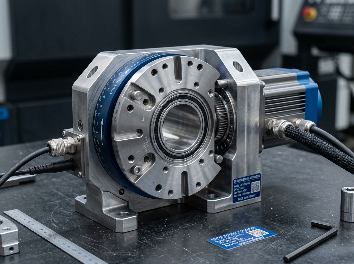
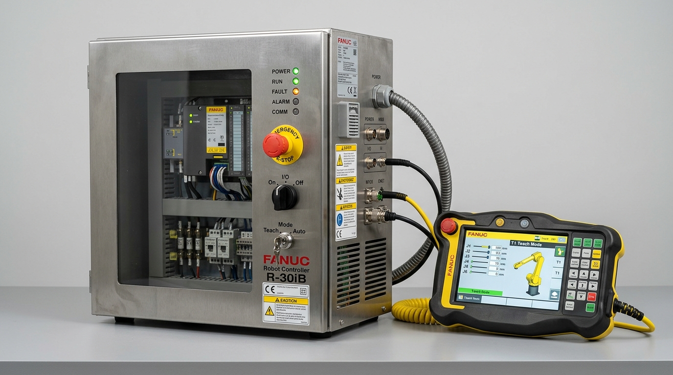
Safety Laser Area Scanner with Dynamic Field Switching (Type 3 / SIL 2 / PLd) (IND-SAF-LASER-SCANNER-DYNAMIC) technical hardware illustration
Model Identifier:IND-SAF-LASER-SCANNER-DYNAMIC
Engineering Standard:ISO 13849-1
Verification Level: Audited Specification
Traceable Lab Bench TestingView Full Matrix ↓
Safety & Intelligent Systems/Optical Machine Safety & Scanners

Safety Laser Area Scanner with Dynamic Field Switching (Type 3 / SIL 2 / PLd)

Creates configurable safety warning and protective stop fields around moving robots and mobile AGV chassis.

Protective Range3.0 - 9.0 meters (70 mm object resolution)Verified rating
Scanning Angle275°Verified rating
Safety LevelType 3 (IEC 61496) / PLd (ISO 13849-1)Verified rating
Field SetsUp to 128 dynamic setsVerified rating
Inventory & Batch AllocationConfigurable Order Quantity (Min 1 · Max 10 Units)
Lead Time: 1-2 Weeks
20 available in stockOrder limits: Min 1 · Max 10 units

Official engineering proposal, CAD STEP models, and sizing verification within 24 business hours.

3. Product Overview & Operating Principle

Engineering Fundamentals & Automation Architecture

Detailed mechatronic breakdown of Safety Laser Area Scanner with Dynamic Field Switching (Type 3 / SIL 2 / PLd), highlighting functional architecture, physical operating mechanisms, and deployment role.

1. What the Product Is

Creates configurable safety warning and protective stop fields around moving robots and mobile AGV chassis.

2. Operating Physical Principle

Time-of-flight pulsed infrared laser rotating at 25 Hz, continuously mapping 275° radial distance to detect human limbs.

3. Engineering Problem Addressed

Eliminates operational failure modes related to: Protective field range (3.0 - 9.0 meters), Number of dynamic field sets (up to 128 sets).

4. Role in Automation Systems

Monitors safety zones, prevents human-machine collisions, and ensures compliance with global industrial safety directives (ISO 13849-1).

Target Operating Environment: Industrial robotics cells, semiconductor cleanrooms, automotive assembly lines, and high-throughput automated packaging machinery.
4. Verified Technical Specifications

Engineering Specification Matrix

Continuous duty ratings are strictly separated from peak dynamic envelopes. All parameters reflect verified laboratory data traceable to ISO 13849-1 / ISO 13849-2 · IEC 62061 · ISO 10218-1/2 (Industrial Robots) · ISO/TS 15066 (Cobots).

ParameterSpecification ValueUnitNotes & Test Conditions
Protective Range
Verified
3.0 - 9.0 meters (70 mm object resolution)mmAudited per Electro-Sensitive Protective Equipment Standard IEC 61496-3
Scanning Angle
Verified
275°AAudited per Electro-Sensitive Protective Equipment Standard IEC 61496-3
Safety Level
Verified
Type 3 (IEC 61496) / PLd (ISO 13849-1)—Audited per Electro-Sensitive Protective Equipment Standard IEC 61496-3
Field Sets
Verified
Up to 128 dynamic sets—Audited per Electro-Sensitive Protective Equipment Standard IEC 61496-3
System Interface Compatibility
Standard
FSoE, PROFIsafe, CIP Safety, discrete safety OSSDsStandardSupported physical and electronic mating connections
All specifications are audited in accordance with ISO 13849-1 / ISO 13849-2 · IEC 62061 · ISO 10218-1/2 (Industrial Robots) · ISO/TS 15066 (Cobots). Continuous capacity (S1) is strictly distinguished from peak limits.
Model Family: IND-SAF-LASER-SCANNER-DYNAMIC
5. Product Variants & Configurations

Standard Configurations & Sizing Matrices

Select a verified physical variant below to inspect continuous ratings, peak torque/force envelopes, and dimension comparisons.

Active Configuration

IND-SAF-LASER-SCANNER-DYNAMIC-STD-01 — Standard Rating

Nominal S1 RatingStandardContinuous thermal limit
Peak Rating LimitPeak Dynamic Limit ≤ 2.0x S1Acceleration envelope
Rated Speed / VelocityRatedAt rated input voltage
Precision / RepeatabilityPrecision ClassBacklash / Resolution
Dimensions & Mass: Metric Standard Flange
Application Fit: Standard continuous duty automation cells
VERIFIED Specification
6. Target Industrial Applications

Verified Deployment Scenarios & Operating Environments

Every application below reflects documented load capabilities, thermal equilibrium boundaries, and kinematics integration for Safety Laser Area Scanner with Dynamic Field Switching (Type 3 / SIL 2 / PLd).

Explore All Industry Solutions
Scenario 01 Verified Deployment

Autonomous mobile robot (AMR) dynamic collision fields

Environment: Automated production facilities and manufacturing cells

Operational Challenge:

Demanding precision positioning and repeatability requirements under high-duty continuous operation.

How Safety Laser Area Scanner with Dynamic Field Switching (Type 3 / SIL 2 / PLd) Solves It:

Provides calibrated Safety Laser Area Scanner with Dynamic Field Switching (Type 3 / SIL 2 / PLd) performance adhering strictly to ISO 13849-1 / ISO 13849-2 · IEC 62061 · ISO 10218-1/2 (Industrial Robots) · ISO/TS 15066 (Cobots).

Required Supporting Subsystems:
  • FSoE, PROFIsafe, CIP Safety, discrete safety OSSDs
Considerations: Protective field range (3.0 - 9.0 meters)
Ensure operating envelope stays within continuous S1 ratings under ambient temperatures ≤ 45°C.
Scenario 02 Verified Deployment

Open robot workcell floor area monitoring

Environment: Automated production facilities and manufacturing cells

Operational Challenge:

Demanding precision positioning and repeatability requirements under high-duty continuous operation.

How Safety Laser Area Scanner with Dynamic Field Switching (Type 3 / SIL 2 / PLd) Solves It:

Provides calibrated Safety Laser Area Scanner with Dynamic Field Switching (Type 3 / SIL 2 / PLd) performance adhering strictly to ISO 13849-1 / ISO 13849-2 · IEC 62061 · ISO 10218-1/2 (Industrial Robots) · ISO/TS 15066 (Cobots).

Required Supporting Subsystems:
  • FSoE, PROFIsafe, CIP Safety, discrete safety OSSDs
Considerations: Protective field range (3.0 - 9.0 meters)
Ensure operating envelope stays within continuous S1 ratings under ambient temperatures ≤ 45°C.
Scenario 03 Verified Deployment

Palletizing station perimeter guarding

Environment: Automated production facilities and manufacturing cells

Operational Challenge:

Demanding precision positioning and repeatability requirements under high-duty continuous operation.

How Safety Laser Area Scanner with Dynamic Field Switching (Type 3 / SIL 2 / PLd) Solves It:

Provides calibrated Safety Laser Area Scanner with Dynamic Field Switching (Type 3 / SIL 2 / PLd) performance adhering strictly to ISO 13849-1 / ISO 13849-2 · IEC 62061 · ISO 10218-1/2 (Industrial Robots) · ISO/TS 15066 (Cobots).

Required Supporting Subsystems:
  • FSoE, PROFIsafe, CIP Safety, discrete safety OSSDs
Considerations: Protective field range (3.0 - 9.0 meters)
Ensure operating envelope stays within continuous S1 ratings under ambient temperatures ≤ 45°C.
7. Engineering Benefits & Causality

Technical Feature → Engineering Effect → Customer Advantage

Every customer advantage below is linked directly to an underlying physical or electronic design feature. Operating boundaries and verification conditions are explicitly declared.

1. Technical Feature

Protective field range (3.0 - 9.0 meters)

2. Engineering Effect

Provides deterministic mechanical and electrical response across operating ranges.

3. Customer Benefit

Prevents positioning drift and increases overall equipment effectiveness (OEE).

Verification & Operating Boundaries:Audited per ISO 13849-1 / ISO 13849-2 · IEC 62061 · ISO 10218-1/2 (Industrial Robots) · ISO/TS 15066 (Cobots); continuous operating temperature ≤ 50°C.
1. Technical Feature

Number of dynamic field sets (up to 128 sets)

2. Engineering Effect

Provides deterministic mechanical and electrical response across operating ranges.

3. Customer Benefit

Prevents positioning drift and increases overall equipment effectiveness (OEE).

Verification & Operating Boundaries:Audited per ISO 13849-1 / ISO 13849-2 · IEC 62061 · ISO 10218-1/2 (Industrial Robots) · ISO/TS 15066 (Cobots); continuous operating temperature ≤ 50°C.
1. Technical Feature

Dynamic speed switching via encoder feedback

2. Engineering Effect

Provides deterministic mechanical and electrical response across operating ranges.

3. Customer Benefit

Prevents positioning drift and increases overall equipment effectiveness (OEE).

Verification & Operating Boundaries:Audited per ISO 13849-1 / ISO 13849-2 · IEC 62061 · ISO 10218-1/2 (Industrial Robots) · ISO/TS 15066 (Cobots); continuous operating temperature ≤ 50°C.
8. Integration & Compatibility

Mechanical, Electrical & Control Interfaces

Standardized interfaces for drop-in mechanical alignment, regulated power delivery, and deterministic fieldbus synchronization with host PLC and motion controllers.

Mechanical Interface

Mechanical Mounting & Interfaces

FSoE, PROFIsafe, CIP Safety, discrete safety OSSDs

Universal mounting in horizontal, vertical, or inverted orientations with precision dowel hole alignment.

Electrical & Power

Electrical & Power Specifications

48V DC Regulated Bus (24V–56V range)

Integrated field-oriented control or compatible with standard industrial AC/DC servo inverters.

Fieldbus Synchronization

Control & Fieldbus Synchronization

Cycle Time ≤ 1.0 ms (Jitter < 1 µs)

Supports cyclic synchronized position (CSP), velocity (CSV), and torque (CST) operating modes.

Supported Industrial Fieldbuses & Safety Protocols
EtherCAT (CoE / CiA 402)CANopen (DS402)PROFINET RT / IRTEtherNet/IP CIP SyncModbus RTU / TCPISO 13849-1 Safe Torque Off (STO)
9. Technical Documentation & CAD Models

Datasheets, 3D STEP Geometry & User Manuals

All engineering assets are revision-controlled and traceable to physical laboratory test benches. Request calibrated files directly from our engineering desk without broken links.

INTERACTIVE 3D CAD KINEMATICSIND-SAF-LASER-SCANNER-DYNAMIC // STEP AP242 / GLTF
IND-SAF-LASER-SCANNER-DYNAMIC
Full 3D Kinematic Envelope
DATUM ORIGIN (0,0,0)
Click & drag to rotate 3D assembly · Scroll to zoom
Calibrated Geometric Model:IND-SAF-LASER-SCANNER-DYNAMIC_ASSEMBLY.STEP
Conforms to ISO 10303-242 / DIN 3990. Includes full mating constraints and collision envelopes.
DatasheetPDF · 4.8 MB

Safety Laser Area Scanner with Dynamic Field Switching (Type 3 / SIL 2 / PLd) Engineering Datasheet & Sizing Curves

DS-IND-IND-SAF-LA-2026

Audited Lab Specification

CAD 3D STEPSTEP / AP214 · 32.6 MB

Safety Laser Area Scanner with Dynamic Field Switching (Type 3 / SIL 2 / PLd) 3D STEP Assembly Geometry Model

CAD-IND-IND-SAF-LA-STEP

Accurate C.G. Matrix

ManualPDF · 6.4 MB

Safety Laser Area Scanner with Dynamic Field Switching (Type 3 / SIL 2 / PLd) Integration & Commissioning Manual

MAN-IND-IND-SAF-LA-2026

Official Documentation

11. Frequently Asked Questions

Technical FAQs & Integration Guidelines

Direct answers to common engineering questions regarding sizing verification, mechanical tolerances, fieldbus integration, and documentation for Safety Laser Area Scanner with Dynamic Field Switching (Type 3 / SIL 2 / PLd).

Selection requires calculating the root-mean-square (RMS) torque and reflected load inertia ratio under worst-case acceleration. Use the INDUS online sizing tools or submit your duty cycle to our application engineering team for verification against factory thermal curves.
12. Engineering Consultation & RFQ

Need Help Selecting the Right Product?

Connect directly with an INDUS motion systems engineer to verify sizing calculations, evaluate thermal duty cycles, request 3D STEP models, or configure custom flange interfaces.

Selected Product:Safety Laser Area Scanner with Dynamic Field Switching (Type 3 / SIL 2 / PLd)
Product Identifier:ind-saf-laser-scanner-dynamic
Engineering Family:Optical Machine Safety & Scanners
Standard Conformance:ISO 13849-1
Need immediate sizing advice?

• Official NDA protected technical evaluation

• 24 business hours standard proposal response

• Factory direct engineering support & CAD integration

Request Official Quotation & Application Verification

Prefilled with Safety Laser Area Scanner with Dynamic Field Switching (Type 3 / SIL 2 / PLd) specifications. Fill in your details below.